Download
1 / 69
690 likes | 796 Views
Using the Assembler. Chapter 4 Operators and Expressions JMP and LOOP Instructions Addressing Modes Using a Link Library. Producing the .lst and .map files. With MASM 6.11, the ML command assemble and links a .ASM file ml hello.asm It produces a .OBJ file and a .EXE file

E N D
Using the Assembler Chapter 4 Operators and Expressions JMP and LOOP Instructions Addressing Modes Using a Link Library
Producing the .lst and .map files • With MASM 6.11, the ML command assemble and links a .ASM file • ml hello.asm • It produces a .OBJ file and a .EXE file • Option /Zi produces debugging info for CV • Option /Fl produces a source listing • Option /Fm produces a map file • Ex: to produce all of these, type (with spaces) • ml /Zi /Fl /Fm hello.asm
Examining the .lst and .map files • hello.lst • The R suffix of an address indicates that it is relocatable (resolved at loading time) • With the .model small directive, MASM aligns the segments in memory in the following way: • the stack segment is align at the next available paragraph boundary (ie: at a physical address divisible by 10h) • the code and data segments are aligned at the next available word boundary (ie: at a physical address divisible by 2) • The (relative) starting physical address of the segments are found in the hello.map file
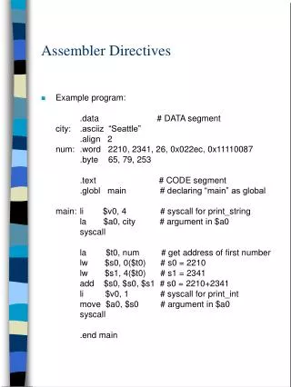
Alignment of the data segment • The offset address of the first data is generally not 0 if the data segment is loaded on a word boundary • Ex: if the code part of hello.asm takes 11h bytes and starts at 30000h. The first data will start at 30012h and DS will contain 3001h. • .data • message db "Hello, world!",0dh,0ah,'$’ • The offset address of message will be 2 instead of 0 (check this with Code View) mov bx, offset message ; BX=2 mov bx, offset message+1 ; BX=3 ...
Alignment of the data segment (cont.) • TASM however will align the data segment at the first paragraph boundary (with the .model small directive) • So the offset address of the first data in the data segment will always be 0 • (like it is indicated in section 4.1.4 of the textbook)
Processor Directives • By default MASM and TASM only enable the assembly of the 8086 instructions • The .386 directive enables the assembly of 386 instructions • instructions can then use 32-bit operands, including 32-bit registers • Place this directive just after .model • Same principle for all the x86 family • Ex: use the .586 directive to enable the assembly of Pentium instructions
Using a Link Library • A link library is a file containing compiled procedures. Ex: irvine.lib contains procedures for doing I/O and string-to-number conversion (see table 5 and appendix e). Ex: • Readint : reads a signed decimal string from the keyboard and stores the corresponding 16-bit signed number into AX • Writeint_signed : displays the signed decimal string representing the signed number in AX • To use these procedures in intIO.asm : • ml irvine.lib intIO.asm
The EXTRN directive • A pgm must use the EXTRN directive whenever it uses a name that is defined in another file. Ex. in intIO.asm we have: • extrn Readint:proc, Writeint_signed:proc • For externally defined variables we use either byte, word or dword. Ex: • extrn byteVar:byte, wordVar:word • For an externally defined constant, we use abs: • extrn true:abs, false:abs
The LOOP instruction • The easiest way to repeat a block of statements a specific number of times • LOOP label • where the label must precede LOOP by less than 127 bytes of code • LOOP produces the sequence of events: • 1) CX is decremented by 1 • 2) IF (CX=0) THEN go to the instruction following LOOP, ELSE go to label • LOOPD uses the 32-bit ECX register as the loop counter (.386 directive and up)
The LOOP instruction (cont.) • Ex: the following will print all the ASCII codes (starting with 00h): • mov cx,128 • mov dl,0 • mov ah,2 • next: • int 21h • inc dl • loop next • If CX would be initialized to zero: • after executing the block for the 1st time, CX would be decremented by 1 and thus contain FFFFh. • the loop would thus be repeated again 64K times!! Break ...
3–1 DATA ADDRESSING MODES • MOV instruction is a common and flexible instruction. • provides a basis for explanation of data-addressing modes • Figure 3–1 illustrates the MOV instruction and defines the direction of data flow. • Source is to the right and destination the left, next to the opcode MOV. • an opcode, or operation code, tells the microprocessor which operation to perform
Figure 3–1 The MOV instruction showing the source, destination, and direction of data flow.
Figure 3–2 shows all possible variations of the data-addressing modes using MOV. • These data-addressing modes are found with all versions of the Intel microprocessor. • except for the scaled-index-addressing mode, found only in 80386 through Core2 • RIP relative addressing mode is not illustrated. • only available on the Pentium 4 and Core2in the 64-bit mode
Register Addressing • The most common form of data addressing. • once register names learned, easiest to apply. • The microprocessor contains these 8-bit register names used with register addressing: AH, AL, BH, BL, CH, CL, DH, and DL. • 16-bit register names: AX, BX, CX, DX, SP, BP, SI, and DI. • In 80386 & above, extended 32-bit register names are: EAX, EBX, ECX, EDX, ESP, EBP, EDI, and ESI.
Figure 3–3 The effect of executing the MOV BX, CX instruction at the point just before the BX register changes. Note that only the rightmost 16 bits of register EBX change.
Figure 3–3 shows the operation of the MOV BX, CX instruction. • The source register’s contents do not change. • the destination register’s contents do change • The contents of the destination register or destination memory location change for all instructions except the CMP and TEST instructions. • The MOV BX, CX instruction does not affect the leftmost 16 bits of register EBX.
Immediate Addressing • Term immediate implies that data immediately follow the hexadecimal opcode in the memory. • immediate data are constant data • data transferred from a register or memory location are variable data • Immediate addressing operates upon a byte or word of data. • Figure 3–4 shows the operation of a MOV EAX,13456H instruction.
Figure 3–4 The operation of the MOV EAX,3456H instruction. This instruction copies the immediate data (13456H) into EAX. • As with the MOV instruction illustrated in Figure 3–3, the source data overwrites the destination data.
The symbolic assembler portrays immediate data in many ways. • The letter H appends hexadecimal data. • If hexadecimal data begin with a letter, the assembler requires the data start with a 0. • to represent a hexadecimal F2, 0F2H is usedin assembly language • Decimal data are represented as is and require no special codes or adjustments. • an example is the 100 decimal in theMOV AL,100 instruction
The next field to the right is the opcode field. • designed to hold the instruction, or opcode • the MOV part of the move data instruction is an example of an opcode • Right of the opcode field is the operand field. • contains information used by the opcode • the MOV AL,BL instruction has the opcode MOV and operands AL and BL • The comment field, the final field, contains a comment about the instruction(s). • comments always begin with a semicolon (;)
Direct Data Addressing • Applied to many instructions in a typical program. • Two basic forms of direct data addressing: • direct addressing, which applies to a MOV between a memory location and AL, AX, or EAX • displacement addressing, which applies to almost any instruction in the instruction set • Address is formed by adding the displacement to the default data segment address or an alternate segment address.
Direct Addressing • Direct addressing with a MOV instruction transfers data between a memory location, located within the data segment, and the AL (8-bit), AX (16-bit), or EAX (32-bit) register. • usually a 3-byte long instruction • MOV AL,DATA loads AL from the data segment memory location DATA (1234H). • DATA is a symbolic memory location, while1234H is the actual hexadecimal location
Figure 3–5 The operation of the MOV AL,[1234H] instruction when DS=1000H . • This instruction transfers a copy contents of memory location 11234H into AL. • the effective address is formed by adding1234H (the offset address) and 10000H(the data segment address of 1000H times10H) in a system operating in the real mode
Displacement Addressing • Almost identical to direct addressing, except the instruction is 4 bytes wide instead of 3. • In 80386 through Pentium 4, this instruction can be up to 7 bytes wide if a 32-bit register and a 32-bit displacement are specified. • This type of direct data addressing is much more flexible because most instructions use it.
Register Indirect Addressing • Allows data to be addressed at any memory location through an offset address held in any of the following registers: BP, BX, DI, and SI. • In addition, 80386 and above allow register indirect addressing with any extended register except ESP.
Figure 3–6 The operation of the MOV AX,[BX] instruction when BX = 1000H and DS = 0100H. Note that this instruction is shown after the contents of memory are transferred to AX.
The data segment is used by default with register indirect addressing or any other mode that uses BX, DI, or SI to address memory. • If the BP register addresses memory, the stack segment is used by default. • these settings are considered the default forthese four index and base registers • For the 80386 and above, EBP addresses memory in the stack segment by default. • EAX, EBX, ECX, EDX, EDI, and ESI address memory in the data segment by default. • When using a 32-bit register to address memory in the real mode, contents of the register must never exceed 0000FFFFH.
In some cases, indirect addressing requires specifying the size of the data by the special assembler directive BYTE PTR, WORD PTR, or DWORD PTR. • these directives indicate the size of the memory data addressed by the memory pointer (PTR) • The directives are with instructions that address a memory location through a pointer or index register with immediate data.
Indirect addressing often allows a program to refer to tabular data located in memory. • Figure 3–7 shows the table and the BX register used to sequentially address each location in the table. • To accomplish this task, load the starting location of the table into the BX registerwith a MOV immediate instruction. • After initializing the starting address of the table, use register indirect addressing tostore the 50 samples sequentially.
Figure 3–7 An array (TABLE) containing 50 bytes that are indirectly addressed through register BX.
Base-Plus-Index Addressing • Similar to indirect addressing because it indirectly addresses memory data. • The base register often holds the beginning location of a memory array. • the index register holds the relative positionof an element in the array • whenever BP addresses memory data, both the stack segment register and BP generate the effective address
Locating Data with Base-Plus-Index Addressing • Figure 3–8 shows how data are addressed by the MOV DX,[BX + DI] instruction when the microprocessor operates in the real mode. • The Intel assembler requires this addressing mode appear as [BX][DI] instead of [BX + DI]. • The MOV DX,[BX + DI] instruction is MOV DX,[BX][DI] for a program written for the Intel ASM assembler.
Figure 3–8 An example showing how the base-plus-index addressing mode functions for the MOV DX,[BX + DI] instruction. Notice that memory address 02010H is accessed because DS=0100H, BX=100H and DI=0010H.
Locating Array Data Using Base-Plus-Index Addressing • A major use is to address elements in a memory array. • To accomplish this, load the BX register (base) with the beginning address of the array and the DI register (index) with the element number to be accessed. • Figure 3–9 shows the use of BX and DI to access an element in an array of data.
Figure 3–9 An example of the base-plus-index addressing mode. Here an element (DI) of an ARRAY (BX) is addressed.
Register Relative Addressing • Similar to base-plus-index addressing and displacement addressing. • data in a segment of memory are addressed by adding the displacement to the contents of a base or an index register (BP, BX, DI, or SI) • Figure 3–10 shows the operation of the MOV AX,[BX+1000H] instruction. • A real mode segment is 64K bytes long.
Figure 3–10 The operation of the MOV AX, [BX=1000H] instructon, when BX=1000H and DS=0200H .
Addressing Array Data with Register Relative • It is possible to address array data with register relative addressing. • such as with base-plus-index addressing • In Figure 3–11, register relative addressing is illustrated with the same example as for base-plus-index addressing. • this shows how the displacement ARRAY addsto index register DI to generate a reference toan array element
Figure 3–11 Register relative addressing used to address an element of ARRAY. The displacement addresses the start of ARRAY, and DI accesses an element.
Base Relative-Plus-Index Addressing • Similar to base-plus-index addressing. • adds a displacement • uses a base register and an index register toform the memory address • This type of addressing mode often addresses a two-dimensional array of memory data.
Addressing Data with Base Relative-Plus-Index • Least-used addressing mode. • Figure 3–12 shows how data are referenced if the instruction executed by the microprocessor is MOV AX,[BX + SI + 100H]. • displacement of 100H adds to BX and SI to form the offset address within the data segment • This addressing mode is too complex for frequent use in programming.
Figure 3–12 An example of base relative-plus-index addressing using a MOV AX,[BX+SI=1000H] instruction. Note: DS=1000H
Addressing Arrays with Base Relative-Plus-Index • Suppose a file of many records exists in memory, each record with many elements. • displacement addresses the file, base register addresses a record, the index register addresses an element of a record • Figure 3–13 illustrates this very complex form of addressing.
Figure 3–13 Base relative-plus-index addressing used to access a FILE that contains multiple records (REC).
3–2 PROGRAM MEMORY-ADDRESSING MODES • Used with the JMP (jump) and CALL instructions. • Consist of three distinct forms: • direct, relative, and indirect
Direct Program Memory Addressing • Used for all jumps and calls by early microprocessor; also used in high-level languages, such as BASIC. • GOTO and GOSUB instructions • The microprocessor uses this form, but not as often as relative and indirect program memory addressing. • The instructions for direct program memory addressing store the address with the opcode.
Figure 3–14 The 5-byte machine language version of a JMP [10000H] instruction.
This JMP instruction loads CS with 1000H and IP with 0000H to jump to memory location 10000H for the next instruction. • an intersegment jump is a jump to any memory location within the entire memory system • Often called a far jump because it can jump to any memory location for the next instruction. • in real mode, any location within the first 1M byte • In protected mode operation, the far jump can jump to any location in the 4G-byte addressrange in the 80386 - Core2 microprocessors