Download
1 / 11
110 likes | 129 Views
1. Main Dichroic Beam Splitter (HFT) An HFT XXX[/YYY/...] deflects the indicated laser lines onto the specimen and allows the emitted fluorescent light to pass through. Example: HFT 458/514, HFT UV/488/543/633 (deflects also UV excitation light)

E N D
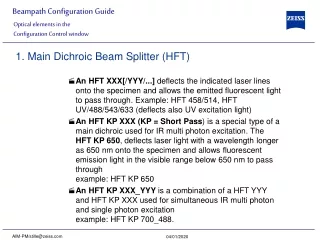
1. Main Dichroic Beam Splitter (HFT) An HFT XXX[/YYY/...] deflects the indicated laser lines onto the specimen and allows the emitted fluorescent light to pass through. Example: HFT 458/514, HFT UV/488/543/633 (deflects also UV excitation light) An HFT KP XXX (KP = Short Pass) is a special type of a main dichroic used for IR multi photon excitation. The HFT KP 650, deflects laser light with a wavelength longer as 650 nm onto the specimen and allows fluorescent emission light in the visible range below 650 nm to pass throughexample: HFT KP 650 An HFT KP XXX_YYY is a combination of a HFT YYY and HFT KP XXX used for simultaneous IR multi photon and single photon excitationexample: HFT KP 700_488. Optical elements in the Configuration Control window AIM-PM/stille@zeiss.com
2. Secondary Dichroic Beam Splitter (NFT) The NFT XXX is used to split the emitted light which will be guided into separate channels. Light with shorter wavelength than XXX nm is deflected, light with longer wavelength passes the NFT. A cascade of NFTs allows to distribute the emission light to more than two channels/detectors. The NFT KP YYY splits emission light the other way round: it transmits light shorter than YYY nm and deflects above YYY nm. Optical elements in the Configuration Control window AIM-PM/stille@zeiss.com
3) Emission Filters (EF) An LP XXX (Long Pass) transmits emission light with wavelengths longer than the indicated threshold value XXX. A KP XXX(Short Pass) transmits emission light with wavelengths shorter than the indicated threshold value XXX. A BP XXX-YYY (Band Pass) transmits emission light within the indicated wavelength band. A BP XXX/YY has a transmission band for emission light with a center wavelength of XXX nm and a width of YY nm. The BG 39 (Blue Green glas) blocks infrared excitation light by absorption. BP ... IR (Band Pass – Infra Red) is a band pass suitable for detection of IR excited dyes. It blocks the IR light. Optical elements in the Configuration Control window AIM-PM/stille@zeiss.com
4) Miscellaneous Plates do transmit light 100%. They are used for a correct beam guidance and will be set automatically. Mirrors do deflect 100% over the whole spectral range and can be used to guide the emission light to selected detectors. Optical elements in the Configuration Control window AIM-PM/stille@zeiss.com
Switch on the suitable lasers for excitation of the dyes in the specimen. For the UV laser and the Argon laser set the tube current of the laser to a value of app. 50% (Excitation, Laser, Output [%]) Example: for Alexa 488 and CY 3 switch on Argon (blue excitation) and HeNe1 (green excitation). Activate the proper laser lines in the Line Active check box, set Transmission [%] for each active line.Example: Select 488 to 5% and 543 to 100% Select a main dichroic beamsplitter (HFT) which deflects the selected laser lines to the specimen Example: HFT 488/543 Check the available emission filters (EM 1- 4) for transmission of fluorescent light from the specimen, in order to identify the channels for detection Example: BP 505-530 in channel Ch 3 for acquisition of green emission and LP 560 in channel Ch 4 for acquisition of red emission. Setup of Single Tracks using single detectors AIM-PM/stille@zeiss.com
Use the secondary beam splitters (NFT 1/2/3) to split and guide the emitted fluorescent light to the detectors (PMTs) of the selected channels (see above). Example: an NFT 545 in NFT 1 position will allow light longer then 545nm to pass to Ch 1 and 4 and deflects light shorter then 545 towards channel Ch 3 (if available) and channel Ch 2. Select a mirror inNFT 3 to guide the red fluorescence to Ch 4. Setup of Single Tracks using single detectors AIM-PM/stille@zeiss.com
Select the proper emission filters in front of the channels and activate channels.Example: select LP 560 in front of Ch 4, and BP 505-530 in front of Ch 3]. Make sure that the active detection bands do not include any of the active laser lines.Example: do not use a BP 505-550 for detection of green emission when using the 543 nm line for green excitation Setup of Single Tracks using single detectors AIM-PM/stille@zeiss.com
Do not forget to turn on detectors. Assign appropriate colors to these active channels.Example: Ch 4 - red (for Cy3 emission), Ch 3 - green (for Alexa488 emission) The Spectra dialog is a big help for checking if the configuration of the beam path was successful. It shows activated laser lines and for each channel the emission range that can be ”seen” by the detector indicated by the corresponding channel color. A gray bar indicates an emission range that is guided into a channel, but the detector is not turned on. When simultaneously detecting more than one fluorescent dye, use channel Ch 4 for detection of the emission with long wavelength, then channels Ch 3 (if available) for medium wavelengths and channel Ch 2 for short wavelengths. Use NFT 3 for separating emission into channels ChS and Ch 4 and NFT 2 for separating emission into channels Ch 2 and Ch 3 Additional hints AIM-PM/stille@zeiss.com
Multitracking is the method of choice for multi fluorescence imaging. It has the advantage to avoid artifacts based on emission crosstalk that occurs when using simultaneous excitation and detection. Laser lines are switched very fast and channels recorded quasi-simultaneously. The configuration of Multiple Tracks follows the same rules described above for single track configuration. The main difference is that each track is configured to excite and detected only one fluorescent dye to prevent cross talking (or two dyes with non overlapping emission spectra). Create a single track for both, Alexa 488 and CY 3 detection separately (see above). Open the Multi Track configuration window. The system displays the Single Track setup as track one. Add a new track. Click on track one, deactivate Ch 4 (red emission detection) and switch off the green laser line (543nm) in the Line Active check box in the Excitation control window. Multitracking configuration AIM-PM/stille@zeiss.com
Click on track two, deactivate Ch 3 (green emission detection) and switch the blue laser line (488) off. To extend the detection band for the green light it is now reasonable to use the BP 505-550 instead of BP 505-530 in track one. This is now possible since the green laser line is turned off during detection of the green fluorescence emission. Use the Spectra window to check the proper settings for each individual track as described above. Multitracking configuration AIM-PM/stille@zeiss.com
Settings can be used for Line or Frame wise Multitracking. In Line mode the lines are scanned in turns for all tracks with the corresponding laser lines turned on exclusively. Preferred for living samples with moving objects. Acquisition time can be reduced using bidirectional scan mode. In Frame mode whole frames are scanned in turns for all tracks with the corresponding laser lines turned on exclusively. This mode can be advantageous for dyes that tend to bleach and need time to recover. There are parameters that can be changed quickly in a line wise Multitracking: Amplifier Gain, Amplifier Offset, Laser Line Attenuation, Any other changes of track settings of the selected tracks, e. g. different filters, dichroics or Detector Gain settings, need a bit more time to be changed, and require Frame mode. There is a fast Frame mode, that requires identical settings of these parameters. In our example it is now possible to use the BP 505-550 also in track two. There is no function of this BP in track two, but it guarantees equal settings in both tracks/channels, which now allows line wise Multitracking. Line and Frame Mode of Multitracking AIM-PM/stille@zeiss.com