Download
1 / 10
180 likes | 648 Views
XTR115 + TPS54062. Objective: Increase the available power for sensor and other external circuitry on a remote 2-wire current loop transmitter.

E N D
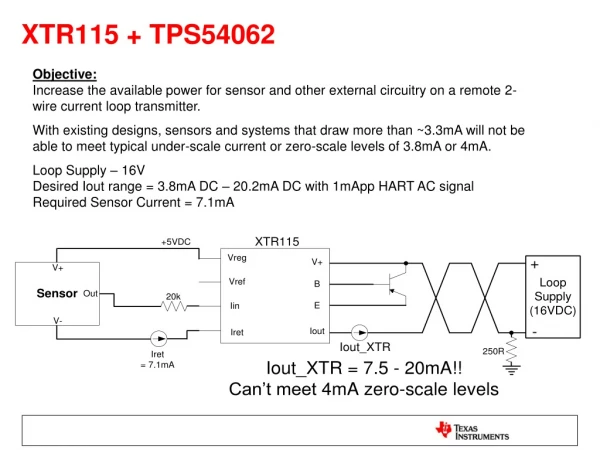
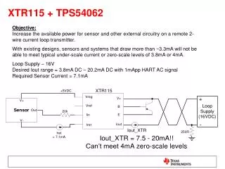
XTR115 + TPS54062 Objective:Increase the available power for sensor and other external circuitry on a remote 2-wire current loop transmitter. With existing designs, sensors and systems that draw more than ~3.3mA will not be able to meet typical under-scale current or zero-scale levels of 3.8mA or 4mA. Loop Supply – 16VDesired Iout range = 3.8mA DC – 20.2mA DC with 1mApp HART AC signalRequired Sensor Current = 7.1mA
XTR115 + TPS54062 Solution:Use low-current buck topology switching power converter to buck down the loop-supply to the required VREG levels. All SMPS current must sink back through IRET of XTR115.
XTR115 + TPS54062 Setup: XTR115 + TPS54062EVM with reduced input capacitance of 1uF Output: 3.8mA DC + 1mAPP 2.2kHz HART signal Results: At 2.2kHz, Max IRET increased to 2.6mA before signal degradation occurred IRET = 2.6mA TPS_IOUT = 7.2mA
XTR115 + TPS54062 Setup: XTR115 + TPS54062EVM with reduced input capacitance of 1uF Output: 3.8mA DC + 1mAPP 2.2kHz HART signal Results: Showing the +3.3V output with the reduced 1uF capacitance, output looks good AC Couple DC Couple
XTR115 + TPS54062 Setup: XTR115 + TPS54062EVM with reduced input capacitance of 0.47uF Output: 3.8mA DC + 1mAPP 2.2kHz HART signal Results: At 2.2kHz, Max IRET increased to 2.85mA before signal degradation occurred IRET = 2.8mA TPS_IOUT = 9mA
XTR115 + TPS54062 Setup: XTR115 + TPS54062EVM with reduced input capacitance of 0.47uF Output: 3.8mA DC + 1mAPP 2.2kHz HART signal Results: At 2.2kHz, Max IRET increased to 2.85mA before signal degradation occurred IRET = 2.85mA TPS_IOUT = 9.25mA
XTR115 + TPS54062 Setup: XTR115 + TPS54062EVM with reduced input capacitance of 0.47uF Output: 3.8mA DC + 1mAPP 2.2kHz HART signal Results: At 2.2kHz, Showing distortion with IRET = 2.9mA IRET = 2.9mA TPS_IOUT = 9.5mA
XTR115 + TPS54062 Setup: XTR115 + TPS54062EVM with reduced input capacitance of 0.47uF Output: 3.8mA DC + 1mAPP 2.2kHz HART signal Results: At 2.2kHz, Showing distortion with IRET = 3mA IRET = 3mA TPS_IOUT = 10mA
XTR115 + TPS54062 Setup: XTR115 + TPS54062EVM with reduced input capacitance of 0.47uF Output: 3.8mA DC + 1mAPP 2.2kHz HART signal Results: Showing the +3.3V output with the reduced 0.47uF capacitance, output looks good AC Couple DC Couple
XTR115 + TPS54062 Setup: XTR115 + TPS54062EVM with reduced input capacitance of 0.47uF Output: 3.8mA DC + 1mAPP 2.2kHz HART signal Results: Showing the +16V input ripple with the reduced 0.47uF capacitance, looks similar when compared to original 0.47uF Input Cap 2.2uF Input cap