Metal Casting Processes
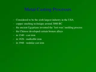
Metal Casting Processes. Casting. One of the oldest manufacturing processes – 4000 B.C. with stone and metal molds for casting copper Pour molten metal into a mold cavity to produce solidified parts that take on the shape of the cavity


Metal Casting Processes
E N D
Presentation Transcript
Casting • One of the oldest manufacturing processes – 4000 B.C. with stone and metal molds for casting copper • Pour molten metal into a mold cavity to produce solidified parts that take on the shape of the cavity • Many different casting processes, each with its own characteristics, applications and materials, advantages, limitations, and costs • Casting can produce complex shapes with internal cavities or hollow sections • Casting can produce very large parts • Competitive with other processes • Good net-shape manufacturing for metals
Solidification of Pure Metals Pure metals solidify at a constant temperature. During freezing the latent heat of solidification is given off. Most metals shrink on solidification and shrink further as the solid cools to room temperature.
Solidification of Pure Metals Direction of heat flow Temperature distribution in a mold part way through solidification. Grain structure for pure metal
Solid Solution Alloys Metal alloys in which one metal is soluble in the other in the solid state. These are also called binary alloys. Copper/Nickel alloys are typical of this type of alloy.
Solidification of Solid Solution AlloysNickel-Copper Alloy Phase Diagram
Mechanical Properties of Copper-Nickel and Copper-Zinc Alloys Figure 4.6 Mechanical properties of copper-nickel and copper-zinc alloys as a function of their composition. The curves for zinc are short, because zinc has a maximum solid solubility of 40% in copper. Source: L. H. Van Vlack; Materials for Engineering. Addison-Wesley Publishing Co., Inc., 1982.
Solidification of Solid Solution Alloys Direction of heat flow Temperature distribution in partial solidified casting. Grain structure for solid solution alloy
Solidification of Eutectic Alloy SystemsLead-Tin Phase Diagram Figure 4.7 The lead-tin phase diagram. Note that the composition of the eutectic point for this alloy is 61.9% Sn-38.1% Pb. A composition either lower or higher than this ratio will have a higher liquidus temperature. The metals have very limited solubility in each other
Iron-Iron Carbide Phase Diagram Figure 4.8 The iron-iron carbide phase diagram. Because of the importance of steel as an engineering material, this diagram is one of the most important of all phase diagrams.
Solidification Patterns Figure 10.4 (a) Solidification patterns for gray cast iron in a 180-mm (7-in.) square casting. Note that after 11 min. of cooling, dendrites reach each other, but the casting is still mushy throughout. It takes about two hours for this casting to solidify completely. (b) Solidification of carbon steels in sand and chill (metal) molds. Note the difference in solidification patterns as the carbon content increases. Source: H. F. Bishop and W. S. Pellini.
Solidification and Cooling • Molten metal solidifies from the mold walls inward • At the mold walls, metal cools rapidly forming a skin, or shell, of fine equiaxed grains • Grains grow in a direction opposite to that of the heat transfer out through the mold, leading to columnar grains • Alloy solidification occurs between the liquidus (TL) and solidus (TS) temperatures, in the freezing range • Alloy solidification leads to dendrites and a mushy zone where both liquid and solid phases are present • After solidification, the casting continues to cool • Grain shapes: • Equiaxed - approximately equal dimensions in 3 directions • Plate-like - one dimension smaller than other two • Columnar - one dimension larger than other two • Dendritic (tree-like)
Solidification Contraction for Various Cast Metals Table 12.1 Normal Shrinkage Allowance for Some Metals Cast in Sand Molds
Cooling Rates • Slow cooling rates (102 K/s) or long local solidification times result in coarse dendritic structures • Fast cooling rates (104 K/s) or short local solidification times result in finer grain structure • Very fast cooling rates (106 to 108 K/s) lead to amorphous alloy structures, or metallic glasses, with no grain boundaries and atoms that are randomly and tightly packed • Smaller grain size leads to increased strength and ductility, decreased microporosity, and decreased tendency for cracked castings • Thermal gradient, G (102 to 103 K/m) • Rate of movement for the liquid-solid interface, R (10-3 to 10-4) • Inoculants, or nucleating agents, can be added to the alloy
Solidification Time Figure 10.10 Solidified skin on a steel casting. The remaining molten metal is poured out at the times indicated in the figure. Hollow ornamental and decorative objects are made by a process called slush casting, which is based on this principle. Source: H. F. Taylor, J. Wulff, and M. C. Flemings. where C is a constant that reflects mold material, metal properties, and temperature Chvorinov’s rule – empirical law for estimating solidification times. Allows comparisons between different shaped castings in the same material and mold types to be made.
Sand CastingExpendable Mold-Permanent Pattern Process • Versatile casting process which can be used for a wide range of shapes • Castings can be produced in all metals • Castings can be made of almost any size • Molds made from sand mixed with a binder – clay, oils, sodium silicate, etc. • Fairly labor intensive process, but relatively economic for small quantities of parts as mold costs are low
Sand Molding Patterns • Pattern Materials • Wood • Plastic • Aluminum • Steel • Cast iron
Shrinkage and Hot Tears Figure 10.11 Examples of hot tears in castings. These defects occur because the casting cannot shrink freely during cooling, owing to constraints in various portions of the molds and cores. Exothermic (heat-producing) compounds may be used (as exothermic padding) to control cooling at critical sections to avoid hot tearing.
Casting Defects Figure 10.12 Examples of common defects in castings. These defects can be minimized or eliminated by proper design and preparation of molds and control of pouring procedures. Source: J. Datsko.
Internal and External Chills Figure 10.13 Various types of (a) internal and (b) external chills (dark areas at corners), used in castings to eliminate porosity caused by shrinkage. Chills are placed in regions where there is a larger volume of metals, as shown in (c).
Ceramic Molds Figure 11.16 Sequence of operations in making a ceramic mold. Source: Metals Handbook, vol. 5, 8th ed. Figure 11.17 A typical ceramic mold (Shaw process) for casting steel dies used in hot forging. Source: Metals Handbook, vol. 5, 8th ed.
Lost Foam or Evaporative Pattern Casting Expandable pattern/ expendable mold process Mold metal evaporates pattern
Investment Casting • Expendable pattern/ expendable mold process • Patterns made from wax or thermoplastic by injection molding • Complex patterns can be built up from multiple pieces or clusters of similar parts can be assembled around a single runner system • Surface finish and accuracy good • Can be used for most metals including those with higher melting points
Investment Casting Figure 11.18 Schematic illustration of investment casting, (lost-wax process). Castings by this method can be made with very fine detail and from a variety of metals. Source: Steel Founders' Society of America. Expendable mold/ expendable pattern process
Investment Casting of a Rotor Figure 11.19 Investment casting of an integrally cast rotor for a gas turbine. (a) Wax pattern assembly. (b) Ceramic shell around wax pattern. (c) Wax is melted out and the mold is filled, under a vacuum, with molten superalloy. (d) The cast rotor, produced to net or near-net shape. Source: Howmet Corporation.
Investment and Conventionally Cast Rotors Figure 11.20 Cross-section and microstructure of two rotors: (top) investment-cast; (bottom) conventionally cast. Source: Advanced Materials and Processes, October 1990, p. 25 ASM International
Centrifugal Casting Process Figure 11.27 Schematic illustration of the centrifugal casting process. Pipes, cylinder liners, and similarly shaped parts can be cast with this process.
Vacuum-Casting Process Figure 11.21 Schematic illustration of the vacuum-casting process. Note that the mold has a bottom gate. (a) Before and (b) after immersion of the mold into the molten metal. Source: From R. Blackburn, "Vacuum Casting Goes Commercial," Advanced Materials and Processes, February 1990, p. 18. ASM International.
Pressure Casting Figure 11.22 (a) The bottom-pressure casting process utilizes graphite molds for the production of steel railroad wheels. Source: The Griffin Wheel Division of Amsted Industries Incorporated. (b) Gravity-pouring method of casting a railroad wheel. Note that the pouring basin also serves as a riser. Railroad wheels can also be manufactured by forging.
Pressure Die Casting Wide range of shapes Lower melting point alloys High mold costs – large quantity product High production rates with short cycle times Extra dies required for trimming flash and runners
(a) (b) Hot- and Cold-Chamber Die-Casting Figure 11.23 (a) Schematic illustration of the hot-chamber die-casting process. (b) Schematic illustration of the cold-chamber die-casting process. Source: Courtesy of Foundry Management and Technology.
Hot Chamber Die Casting • Used for lower melting point alloys (zinc and magnesium) • Mold pressures usually 1000 to 2000 p.s.i, but can be up to 5000.
Cold Chamber Die Casting • Used for higher melting point alloys –aluminum and copper based • Die pressures from 5,000 to 20,000 psi • Die clamping forces at least pressure * project area of part in die closing direction
Squeeze-Casting Figure 11.29 Sequence of operations in the squeeze-casting process. This process combines the advantages of casting and forging.
(c) Single Crystal Casting of Turbine Blades Figure 11.30 Methods of casting turbine blades: (a) directional solidification; (b) method to produce a single-crystal blade; and (c) a single-crystal blade with the constriction portion still attached. Source: (a) and (b) B. H. Kear, Scientific American, October 1986; (c) Advanced Materials and Processes, October 1990, p. 29, ASM International.
Continuous Casting Figure 5.4 The continuous-casting process for steel. Typically, the solidified metal descends at a speed of 25 mm/s (1 in./s). Note that the platform is about 20 m (65 ft) above ground level. Source: Metalcaster's Reference and Guide, American Foundrymen's Society.
Casting Design Considerations • Sharp corners, angles, and fillets should be avoided because they act as stress raisers and may cause cracking and tearing of the metal or dies during solidification • Fillet radii should be between 3 mm and 25 mm (1/8 inch to 1 inch) to reduce stress concentrations and ensure proper liquid-metal flow • Larger fillet radii leads to larger local volumes of material that cool too slowly and may lead to shrinkage cavities Figure 12.1 Suggested design modifications to avoid defects in castings. Note that sharp corners are avoided to reduce stress concentrations.
Casting Design Considerations • Avoid casting designs that will have hot spots, leading to shrinkage cavities and porosity • Maintain uniform cross sections and wall thicknesses when possible • Reduce cross sections when possible to reduce solidification time and save raw materials • Smoothly transition between sections with different cross sectional areas • Consider adding a cored hole if necessary (figure e)
Casting Design Considerations • Use external chills to reduce hot spots (or internal chills if needed) • Avoid large flat areas that may warp during cooling due to temperature gradients or have poor surface finish due to uneven metal flow – use ribs or serrations to break up the flat surface Figure 12.3, 12.4 Source: Steel Castings Handbook, 5th ed. Steel Founders' Society of America, 1980. Used with permission.
Casting Design Considerations • The parting line separating the top and bottom halves of the mold should be along a flat plane and at corners or edges when possible • Parting line location influences ease of molding, cores, support, gating system, etc. Figure 12.5 Source: Steel Casting Handbook, 5th ed. Steel Founders' Society of America, 1980. Used with permission.
Casting Process Economics • Casting costs include labor, materials, machinery, tooling and dies • Preparation time for molds and dies varies, as well as skill required • Furnace and machinery costs depend on the level of automation • Post processing, heat treating, cleaning, and inspecting castings also costs money • Ultimately, per unit costs must be balanced with functional requirements of the cast product • Safety considerations in casting are important! (see page 295)
Casting Design Considerations • Adjust mold dimensions to: • avoid cracking the casting and to account for shrinkage during solidification (typically 1-2%) • account for machining allowances when finishing operations are needed • Set dimensional tolerances as wide as possible while still meeting performance requirements to avoid extra casting costs • Provide draft angles of 0.5 to 2 degrees for outer surfaces of sand castings to allow for removal of the pattern without damaging the mold (0.25 or 0.5 degrees for permanent mold casting) Table 12.1 Normal Shrinkage Allowance for Some Metals Cast in Sand Molds