Download

1 / 96
960 likes | 1.13k Views
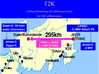
M ARS simulation for T2K neutrino beamline. Yuichi Oyama (KEK). Aug-11-2004@MARS mini-workshop. Contents. (1) Proton beamline. (Ichikawa). (2) Target Station. beam period. after beam stop. maintenance. 130m. (3) Decay Volume. (4) Beam dump / Muon pit. 280m. (Ishida).

E N D
MARS simulation for T2K neutrino beamline Yuichi Oyama (KEK) Aug-11-2004@MARS mini-workshop
Contents (1) Proton beamline (Ichikawa) (2) Target Station • beam period • after beam stop • maintenance 130m (3) Decay Volume (4) Beam dump / Muon pit 280m (Ishida) (5) Cooling water (6) Air/Helium (+) Useful file management
Schematic view of the Target Station 22m 33m Surface building 40tonne crane 11m ground level Concrete Concrete service pit Beam Window Final Focusing section Iron Shielding Underground machine room Decay Volume Helium Container storage of radioactive materials Beam Window Concrete Iron Shielding Buffle Target, 1st Horn 2nd Horn 3rd Horn
Radiation during the beam operation Three Regulations must be satisfied. 20cm Concrete wall fence H < 12.5mSv/h@floor of surface building (1) (3) H < 0.25mSv/h@out of the control area Concrete 4.5m Conc 1m Iron2.2m Iron1.5m (2) H < 5mSv/h@boundary of the concrete Iron1.5m Concrete 3.6m
Calculation of shielding thickness by MARS Instead of 3D real geometry, virtual cylindrical geometry is used to improve statistics. ● ● Calculation with 3D real geometry were performed for the final confirmation using “Black Hole + LEAK and BEG1” technique.
Example: floor of the surface building Target station r z With 4.5m of concrete above the service pit, radiation at floor of the surface building satisfy H<12.5mSv/h
Residual Dose after beam stop After beam stop and ventilation, we must access this area Machine room Service Pit After 1 year operation and 1 day cooling with 0.75MW, the residual dose at the top of the iron shielding is ~0.1 mSv/h We can enter and work in the service pit.
Exchange of the target and/or horn Open the top of the beamline shielding ● Broken target/horn is highly radioactivated, and must be kept in the storage of radioactive materials for several years. ● The shielding also must be kept in the storage during the exchange ● Target station : Cross-sectional view Target station : top view storage of radioactive materials
0.1mSv/h Concrete 1m 22mSv/h 0.56Sv/h Iron 2.2m 0.65Sv/h Aluminum 0.2m Residual dose of the Shielding ● RESIDUAL DOSE of the shielding in the MARS output (1 year operation, 1 day cooling, 0.75MW) Use of Al surface reduce the radiation about one order of magnitude. ● Further calculation is needed after the “scenario” is fixed. ●
Residual dose of the Target/Horn Residual dose of 3cmF x 90cm Carbon Graphite target (in a Al container) and 1st magnetic horn is calculated. ● 50GeV 0.75MW proton After 1 year operation (1)NMTC/JAM(nmtclib95) + DCHAIN-SP + QAD-CGGP2 (2)Hadron fluence(MARS) + cross section(9mb) + 7Be life Horn must be kept in the storage for more than 10 years. ●
30-40 m downstream of target station 5mSv/h log(H(mSv/particle)) 5.5m He Concrete Concrete thickness (m) Calculation ofDecay VolumeShielding As the target station, virtual cylindrical geometry is used in the MARS calculation. ● 5.0~5.9m of concrete and additional ~6m of soil are needed to satisfy concrete and soil surface condition ●
To 2nd machine building Management of Cooling Water ● Regulation : Radioactive water can be exhausted to outside (ocean) if radioactivity is less than 15Bq/cc. Radioactive primary cooling water is circulated only in the underground control area during the beam period. ● Target/Horn cooling Heat exchange Primary cooling water system Secondary cooling water system Third cooling water system
Disposal Scenario of Radioactive Water ● After 20days operation, all radioactive water is transferred to a DP tank in the disposal system. They are mixed with fresh water in the dilution tank. After measurement of radioactivity in the dilution tank, the water can be disposed. ● MARS 1 liter of cooling water for target is exposed to 8x10⁻³/cm2/p of neutron fluence. 2.3GBq of 3H are produced in 20days of 0.75MW operation. To satisfy < 15Bq/cc, 150m3 of dilution water is needed. ● ● We need a capacity of ~600m3 to dispose all together. If we make 60m3 dilution tank, we must repeat the dilutions 10 times.
marsmain.f Useful file management mars.inp-00000 (MARS.INP) One argument is added and used as file number System clock is used as random number seed GUI mode %rmars-bnab-fems-linux 0 %rmars-bnab-fems-linux 1 ; rmars-bnab-fems-linux 2 2 jobs with different random number seeds are submitted. mars.out-00001 and mars.out-00002 are created.
Summary Calculation of shielding Virtual cylindrical geometry is used in the first step. ● Black hole/LEAK and BEG1 technique is employed for the final confirmation. ● Residual dose “RESIDUAL DOSE” in MARS.OUT is used for large volume. ● For small volume, hadron fluence from MARS is used with cross section and lifetime. ● Water and Air/Helium Total radio-activation is calculated from hadron fluence. ● file management One argument as file number and system clock as random number seed in marsmain.f. ●
TS underground machine room Beam Dump machine room Decay Volume Heat exchange Heat exchange Disposal Scenario of Radioactive Water ● After 20days operation, the all radioactive water is transferred to a DP tank in the disposal system. The cooling system for the decay volume is used for this purpose (to save money). They are mixed with fresh water in the dilution tank. ● Primary cooling water from Target/Horn Primary cooling water from Beam Dump DP tank Fresh water After measurement of radioactivity in the dilution tank, the water can be disposed. It takes 1 or 2 days for the measurement. ● Dilution tank Disposal line
Summary of cooling water and their radio-activation 0.75MW , 20days operation ● We need a capacity of ~600m3 to dispose all together. If we make 60m3 dilution tank, we must repeat the dilutions 10 times. We must also consider a possibility to confine the primary cooling water in the radiation control area forever. ●
Ventilation of Air and Helium Regulation : Radioactive gas (air/Helium) can be ventilated to environment if radioactivity is less than 5mBq/cc. ● Air in the low radioactivity area (e.g. surface building) is always ventilated even during the beam period. ● High radioactivity area (e.g. underground control area) is closed in the beam period. ● After the beam stop, high radioactive air/Helium must be mixed with fresh air and ventilated gradually if the radioactivity exceed 5mBq/cc.
Summary of Air/Helium and their radio-activation 0.75MW , 20days operation sair=30mb, sHe=1.2mb, Ventilation : 8000m3/h, < 5mBq/cc A : Ventilate during beam period; B : Ventilate directly after beam stop C : Ventilate by mixing with fresh air after beam stop
KEK Radiation Related Topics Yuichi Oyama (KEK) for neutrino beam construction subgroup and target monitor subgroup Nov-11-2003@NBI2003
Open the shielding 3m Requirement for the boundary during the maintenance MCNP is used. g-ray source are ● defined on the Al tunnel surface. 0.75MW 1-year operation, 1-day cooling 0.25mSv/h 0.4Sv/h Radiation from residual dose in the tunnel is satisfactory small. ●
Radiation behind the Beam Dump At the muon pit, muons from p→nm must be measured with energy threshold of 2~5GeV to study neutrino property. ● Copper 1.5m + Iron 1.5m + concrete 0.5m satisfy this requirement. The threshold for the muons is Eth~4.5GeV ● The residual dose in the muon pit(30days beam, 1 day cooling, 0.75MW) is 0.2mSv/h. ● ● We can enter the muon pit after the beam stop.
Radiation Control Area 低温設備 Target Station Control area (class-1) 2nd machine room Control area (class-1) Control area (class-2)
Determination of the control area boundary by MCNP Neutron sources are defined on the floor, and the dose above the floor is adjusted to be 12.5mSv/h. ● Surface building Top view 12.5mSv/h 0.25mSv/h We need 10m between the surface building and the fence ●
Radiations in the Proton Beamline Following energy loss are assumed from our experience. ● Arc Section Preparation Section 0.75kW point loss 1W/m line loss H < 5mSv/h (line loss) and Regulations ● H < 11mSv/h (point loss) at boundary of the concrete H < 0.25mSv/h at surface of the Soil Soil Final Focusing 0.25kW point loss Concrete
Example : Radiation in the Access Tunnel For more complicated geometry, MARS simulation is employed. ● H~0.5mSv/h The graphical view of the calculation shows that the ‘kink’ of the access tunnel effectively reduce the radiation. ●
Example : Shielding around the tunnel The thickness of the shielding is calculated by the Moyer’s formula and MARS simulation. ● 1.2mSv/h 0.25mSv/h 6.2m soil 11mSv/h 5.6m soil 2.5m concrete 0.05mSv/h 2.3m concrete 5.0m air 2.5m air Arc section Final Focusing section
空気・ヘリウムの放射化 0.75MW20日運転後(反応断面積s=30mb) 排気基準:5mBq/cc以下
1.2mSv/h 0.062mSv/h 0.25mSv/h 0.05mSv/h
Calculation of Decay Volume Shielding As the target station, virtual cylindrical geometry is used in the MARS calculation. ●
空気の管理 上屋内(8300m3): 運転時立入り可、常時排気 • サービスピット(230m3) • 及び地下機械室(330m3) • 運転時立ち入り不可 • 運転時:循環(冷却) • 停止時:排気→換気 ヘリウム容器(135m3) 立ち入り不可 ヘリウム陰圧保持、循環(冷却) • 放射化物保管庫(780m3): • 立ち入り不可 • 運転時:循環? • 停止時:排気→換気
トンネル断面図 1.2mSv/h 0.062mSv/h 0.25mSv/h 0.05mSv/h アーク部 フォーカス部 http://jnusrv01.kek.jp/jnu/zumen/TunnelDanmen.031006.dwg
Disposal scenario for radioactive water • Radioactive water by 20 days operation • TS(0.8m3,5.9GBq) • DV(1.1m3,3.3GBq) • DUMP(?) • 600m3+200m3? if diluted into 15Bq/cc DP tank ~10m3 water • Dilution tank(s): # of check/disposal • 800m3: once / 20 days • 200m3: 4 times / 20 days • 40m3: 20 times / 20 days Dilution tank(s) Disposalline
放射線管理区域 低温設備 第二機械室 第一種管理区域 ターゲットステーション 第一種管理区域 第二種管理区域(案) (要調整)
サブトンネルA,B <0.25mSv/h (蓋の下で0.51mSv/h) 2x10⁻³mSv/h http://jnusrv01.kek.jp/jnu/www/zumen/Neutrino.031003.dwg
Radiations in the proton beamline Energy loss in the beamline are expected from our experience. (Numerical calculation is difficult or even impossible.) ● Preparation Section 0.75kW point loss Arc Section 1W/m line loss Final Focusing 0.25kW point loss
熱量の評価:アルミに170kW/16m、 鉄に40kW/16m • アルミ(1.0m~1.2m):170kW • 鉄1(1.2m~1.4m):36.9kW • 鉄2(1.4m~1.6m):2.4kW • 鉄3(1.6m~1.8m):0.5kW • 鉄4(1.8m~2.0m):0.1kW
Cooling system for Aluminum wall コンクリート シールド 水冷管 鉄シールド (4MW時追加) アルミ容器 空冷面 鉄シールド内面 鉄シールド中間 鉄シールド外面 鉄シールド コンクリートシールド
常時排気 外気 スタック HEPA フィルター 除塩 フィルター 停止時 希釈排気 運転時循環 クーリングユニット 運転時循環 Air Circulation/Ventilation system
ターゲットステーション上屋 地下機械室 開帳時シールド置場 予備ホーン等? 22m 開帳時 操作小屋? トレーラー 出入り口、 汚染検査室 (2x4m) 放射化物保管庫 33m
Cooling water system for Target/Horn To 2nd machine building Heat exchange Primary cooling water system Secondary cooling water system Third cooling water system 0.75MW, 20days operation
冷却水の管理:地下機械室 地下機械室 FF部 DV 放射化物保管庫 • ターゲット • 一次冷却水(0.01m3,28kBq/cc)のポンプ+タンク、 • 熱交換器(~30kW)、二次冷却水のポンプ+タンク • ホーン • 一次冷却水(0.6m3,5kBq/cc)のポンプ+タンク、 • 熱交換器(~30kW)、二次冷却水のポンプ+タンク • 鉄シールド+アルミヘリウム箱 • 一次冷却水(数m3?,数kBq/cc?) • のポンプ+タンク、熱交換器(~200kW) • (二次系はFF部と共通) • ディケイボリューム • 一次冷却水(3m3,数kBq/cc) • のポンプ+タンク、熱交換器(~200kW) • (二次系はFF部と共通) • 排水は地下機械室よりディケイボリュームを通って下流のDPタンクへ
第三ホーン 第二ホーン 第一ホーン ビーム 0.75MW ターゲット