Download
1 / 14
140 likes | 170 Views
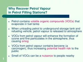
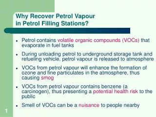
Explore the comprehensive testing analysis of cylinders used as buffers in hydrogen filling stations, aiming to identify the relation between pressure cycle amplitude and number of cycles to failure for different cylinder designs. Testing methodology, results, and analysis are discussed, confirming the validity of the ISO/CD 19884 formula for shallow and deep cycles. This study is essential for ensuring the safety and efficiency of hydrogen storage in filling stations.

E N D
Cylinders and Tubes used as Buffers in the Filling Stations ICHS, Yokohama (Japan) l October 21st ,2015 Hervé BARTHELEMY, Ph.D. - Air Liquide Alberto AGNOLETTI - Faber
Hydrogen at Air Liquide Air Liquide ispresentworldwide on all segments of HydrogenEnergysupplychain H2 Production H2 Supply chain Markets Safety/Standards/Regulations Innovativegasstorage & Packaging 350-700 bar charging stations for mobility > 1000 trailers SMR, Electrolysis purification, liquefaction Cryogenic tank Pipelines About 200 plants >9 B Nm3/yr > 1800 km Hundred of thousands of 200 bar cylinders Fuel cells for alternative power supply
Summary • Introduction • Tests performed on cylinders • Test results • Analysis of the results • Conclusion
Introduction Buffers: key components for hydrogen filling stations • No international standards whereas many standards exist covering Types 1,2,3 & 4 used for transport of gas or on-board fuel tanks Type of cylinders to be used Pressure level Cost Spaceavailable
Introduction Suggestion : To use the cylinders approved for transport of gas or on-board applications as buffers Transportable or on-boardcylinders ≠ Buffers Cycledfrom a lowpressure to a highpressureduring service Cycledfromrelativelyhigh pressure to the MAWPmany times per day To request to pass millions of cycles at low pressure amplitude when developing a standard IMPRACTICAL
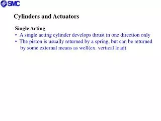
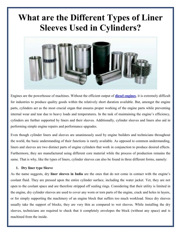
Tests performed on cylinders Aim: To identify the relation between pressure cycle amplitude and number of cycles to failure for different cylinder designs Type 1 cylinder designed to ISO 9809-1 Type 2 cylinder designed to ISO 11119-1 Type 3 cylinder designed to ISO 11119-2
Tests performed on cylinders • Methodology: for each cylinder design: 3 groups of 5 cylinders are taken from one batch and are pressure cycled at different pressure amplitude: • 5 cylinders are pressure cycled from 20 to 450 bars • 5 cylinders are pressure cycled from 20 to 390 bars • 5 cylinders are pressure cycled from 20 to 300 bars • 5 cylinders are pressure cycled from 150 to 300 bars A total of 60 cylinders were pressure cycled.
Test results • Type 1 cylinders
Test results • Type 2 cylinders
Test results • Type 3 cylinders
Analysis of the results • Comparison to the theoretical formula given in ISO/CD 19884 Number of cycles Pressure amplitude Number of cycles (1 = average of number of cycles at pressure amplitude of 150 bar) Pressure amplitude (bar)
Analysis of the results • Last version of ISO/CD/19884 prepared by ISO/TC 197/WG 15 proposes: number of shallow cycles equivalent to number of full cycles required in a given standard variation of pressure during a given actual (shallow) pressure cycle number of (shallow) pressure cycle corresponding to ΔPi pressure amplitude during the (full) cycle tests as specified in the reference standard For pressure vessels to ISO 11120, the number of full cycles shall be taken as 120000 cycles at Ph
Conclusion • Aim of the tests: To identify the relation between Pressure cycle amplitude and Number of cycles to failure for different cylinder designs • Test have been performed on Type 1, Type 2 and Type 3 cylinders • 60 cylinders tested • From 20 to 450 bars, from 20 to 390 bars, from 20 to 300 bars and from 150 to 300 bars • Conclusion: Confirmation of the validity of the formula used in ISO/CD 19884 for the shallow and deep cycles:
End of presentation Thank you for your attention