Top-down Design
540 likes | 800 Views
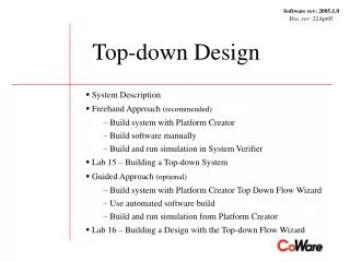
Software rev: 2005.1.0 Doc. rev: 22Apr05. Top-down Design. System Description Freehand Approach (recommended) Build system with Platform Creator Build software manually Build and run simulation in System Verifier Lab 15 – Building a Top-down System Guided Approach (optional)

Top-down Design
E N D
Presentation Transcript
Software rev: 2005.1.0 Doc. rev: 22Apr05 Top-down Design System Description Freehand Approach (recommended) Build system with Platform Creator Build software manually Build and run simulation in System Verifier Lab 15 – Building a Top-down System Guided Approach (optional) Build system with Platform Creator Top Down Flow Wizard Use automated software build Build and run simulation from Platform Creator Lab 16 – Building a Design with the Top-down Flow Wizard
To illustrate top down design, we will build a small system. This is the block diagram. AddrBits / DataBits Hardware Platform Memory Location (Size) System Specification (Application UT Description) i_AHB ROM Processor 20 / 32 0x0 (0x100000) Top 32 / 32 Instruction 32 / 32 Software Block Hardware Block Data RAM 20 / 32 0x400 0000 (0x100000) appSW1 appHW1 port_outMaster port_inSlave port_inSlave port_outMaster Tube 1 / 8 0x8000 0000 (0x2) port_inMaster port_outSlave i_Clock i_Reset A simple system to perform shift operations on unsigned int data
You are provided libraries, scripts and files for building the system trainClass/ Working directory library/ topdown/ Application/ Platform/ Scripts/ Software/ Top/ BuildApplication.tcl IPE/ Boot/ build/ BuildPlatform.tcl BuildTopDownSystem.tcl Auxiliary/ peripherals/ Makefile Makefile boot.s sim AuxiliaryLib.xml PeripheralsLib.xml BuildAuxLib.tcl BuildPeriphLib.tcl ARM_IPE_sw_driver.h Scripts for building the components include/ include/ ARM_IPE_sw_driver.cpp src/ src/ The executable software image Auxiliary and Peripheral block libraries - clock, memory, display Software source to run on the platform
Guided approach Free-hand approach Two approaches can be mixed. Build system with TopDown Wizard Build system without TopDown Wizard Make use of Automated Software build Build Software manually Build and run simulation In Platform Creator Build and run simulation In SV Two alternative approaches will be shown to build and simulate the system
To build the system, you will perform these steps in Free-hand Approach Platform Creator: 1. Open the Platform 2. Open or Import the System Specification 3. Open the Scenario Library 4. Partition blocks to software on the core 5. Resolve abstract channels 6. Create the Memory Map 7. Check the design 8. Export the design 9. Save a project file System Software: 10. Make the System Software Simulation: 11. Build and run simulation
1. Open the platform project file. a. Select File->Open… b. Navigate to topdown/Platform directory c. Select the platform_ARM926.xml project file d. The platform blocks appear in the library drawer
2. Open and merge the system specification a. Select File->Open… b. Navigate to topdown/Application directory c. Select the application.xml project file d. Set checkbox to merge with current system e. The system blocks appear in the library drawer
g. Drag and drop under HARDWARE For convenience, flatten the system specification by moving the blocks to the hardware top level top1 – Delete if you wish platform top1 appSW1 appHW1 h. Position the system specification blocks f. Select the blocks
3. Open the Scenario Library in preparation for interface synthesis a. Select Library->Open… b. Navigate to scenario library location c. Select the AMBA HWSW library d. The scenario blocks become available in the library window
a. Drag and drop the appSW1 block onto the SOFTWARE text to the right of the icon 4. Partition the specification by assigning the appSW1 block to the software portion of the system appSW1 appHW1 When finished, the System Diagram will look like this
A software device driver will write to this memory mapped port These ports are masters and must cause an interrupt of the core, which in turn, will cause an interrupt service routine to read from a memory address As a result of the partitioning, the connections are broken and must be resolved • Two basic types of HW/SW Interface Synthesis to resolve the abstract channels: • Memory mapped (MM) SW is the master • Interrupt driven (ITR) HW is the master The unresolved ports must be connected to the software block on the processor core appHW1 Interface Synthesis produces a HW part and a SW part. The HW part is bus specific. The block is a bridge between a specific bus node and a CoWare handshake protocol on the SW application side. The SW part is core specific. The block contains the SW drivers. The appSW1 block now appears under the SOFTWARE hierarchy
5. Platform Creator will resolve the abstract channels by using scenarios available from the scenario library a. Select the port_inSlave port on the appHW1 block appHW1 b. Pop up the menu with the right mouse button and select the Enable Handshake scenario
The result of the interface synthesis is the instantiation of a hardware interface block and the software device driver The hardware interface block is instantiated and connected to the hardware port. appHW1 The software device driver is instantiated and connected to the software port.
Interface synthesis for the master ports produces hardware and software blocks to implement an Interrupt-driven scenario c. Select the Full Handshake Scenario for the port_outMaster and port_inMaster ports appHW1 The hardware interface blocks are instantiated and connected to the port_outMaster and port_inMaster ports. The software device drivers are instantiated and connected to the software ports.
Add an interrupt priority encoder from the scenario library appHW1 d. From the scenario library, add an Interrupt Priority Encoder(IPE) block with two inputs. Note: In the diagram, we have repositioned the ports of the added block.
Connect the HW interface blocks AHB port,clk port, andreset port, respectively AHB nIRQ connection is externalized from the hierarchy of the core appHW1 clk reset g. Connect the HW interface blocks to their corresponding locations. h. Check connections by selectingCheck->Check Connections.
Configure template arguments on the hardware driver blocks e. Select the appHW1_port_outMaster_driverblock in the editing window and set the delay Template Argument to 100000 appHW1 f. Set the delay for theappHW1_port_inMaster_driverblock to 0 Parameter Editor
6. There are two ways to complete the Memory Map 1. Create the memory map with Platform Creator Select the “Memory Map Table” tab in the Details Window 2. Read in an existing memory map file Select Tools->Import Architecture File… AHB Map i_Tube/p 0x8000 0000 hw_driver_2itr / p_AHB 0x4000 0c00 This is the memory map for our example: The platform comes with a memory map specifying these addresses You must add these targets and addresses to the memory map outMaster_driver/ p_AHB 0x4000 0800 inMaster_driver/ p_AHB 0x4000 0400 appHW1/port_inSlave 0x4000 0000 RAM Byte addressable 0x400 0000 ROM Byte addressable 0x0
Click on Memory Map Table to view the platform memory map Targets Initiators appHW1 This target is reachable by this initiator at the specified address Initiators Cells a. Click on Memory Map Table Targets
Add the application targets to the memory map table b. Select target port. Click right mouse button to pop up the menu. appHW1 c. Select Add to Memory Map Table. The target appears in the next row of the memory map table.
Enter addresses in the memory map table cells d. Make these cells unreachable by the initiators. - Select the cell. - Click right mouse button to pop up the menu and select Remove Link appHW1 e. Double click on a cell. Enter the address and press the Enter key. Note: To remove an unwanted address from a cell, select Remove Link and Set Unreachable from the pop up menu.
The exported memory map looks like this instanceName type access size endianess portWidth mem_map device HARDWARE.appHW1.port_inSlave ram rw 0x1 litend 32; device HARDWARE.appHW1_port_inMasterMY_HW_SUFFIX.p_AHB ram rw 0x4 litend 32; device HARDWARE.appHW1_port_outMasterMY_HW_SUFFIX.p_AHB ram rw 0x4 litend 32; device HARDWARE.i_AHB_IPE_hw_priority_hw_driver_2itr.p_AHB ram rw 0x4 litend 32; device HARDWARE.i_Core.i_DTCM.DATA ram rw 0x4000 litend 32; device HARDWARE.i_Core.i_ITCM.DATA ram rw 0x4000 litend 32; device HARDWARE.i_RAM.p_AHB ram rw 0x100000 litend 32; device HARDWARE.i_ROM.p_AHB ram rw 0x100000 litend 32; device HARDWARE.i_Tube.p ram rw 0x2 litend 32; core HARDWARE.i_Core.i_ARM926 IAHB HARDWARE.i_ROM.p_AHB 0x0 HARDWARE.i_RAM.p_AHB 0x4000000 HARDWARE.i_Tube.p 0x80000000 HARDWARE.appHW1.port_inSlave 0x40000000 HARDWARE.appHW1_port_outMasterMY_HW_SUFFIX.p_AHB 0x40000800 HARDWARE.appHW1_port_inMasterMY_HW_SUFFIX.p_AHB 0x40000400 HARDWARE.i_AHB_IPE_hw_priority_hw_driver_2itr.p_AHB 0x40000c00 , DAHB HARDWARE.i_ROM.p_AHB 0x0 HARDWARE.i_RAM.p_AHB 0x4000000 HARDWARE.i_Tube.p 0x80000000 HARDWARE.appHW1.port_inSlave 0x40000000 HARDWARE.appHW1_port_outMasterMY_HW_SUFFIX.p_AHB 0x40000800 HARDWARE.appHW1_port_inMasterMY_HW_SUFFIX.p_AHB 0x40000400 HARDWARE.i_AHB_IPE_hw_priority_hw_driver_2itr.p_AHB 0x40000c00 , ITCM_DATA HARDWARE.i_Core.i_ITCM.DATA 0x0 , DTCM_DATA HARDWARE.i_Core.i_DTCM.DATA 0x0 ; Initiators Core Instance Name Targets
7. Check the System The occurrence of warnings or errors will cause a message window to open. You may or may not need to correct warnings, but you must correct errors.
8. Export the System Specify a directory to output the files.
9. Save your work as a Project File Export: writes out several files (SystemC source files, memory map and scripts) that will be used to build a simulation. Save: creates a “System Project File” (.xml) system.xml The memory architecture file mem_map Project file Scripts for building the simulation sim.tcl The top level block and sc_main function HARDWARE.cpp The bus model exported by the bus library handler CwrModule_HARDWARE_i_AHB.cpp System specification software blocks and drivers SOFTWARE_ARM926EJS_AHB_Model.cpp
10. Make the System Software topdown Hardware exported by Platform Creator . . . Platform/ Top/ Software/ IPE/ Boot/ build/ CwrModule_HARDWARE_i_AHB.cpp boot.s . . . a. Check that boot.s has been compiled. If not, make Makefile HARDWARE.cpp Software exported by Platform Creator ARM_IPE_sw_driver.h . . . ARM_IPE_sw_driver.cpp sim.tcl c. %make SOFTWARE_ARM926EJS_AHB_Model/ Makefile Existing ARM boot and initialization code. Makefile.include Makefile.include SOFTWARE_ARM9… SOFTWARE_ARM926EJS_AHB_Model.cpp Link to ... sim b. Create links to exported software The executable software image
The final step is to build and run the simulation. The key files are: .h & .cpp: design source files sim.tcl: simulation build script sim.fof: list of all .cpp files mem_map: memory architecture file .scshrc: optional TCL file exportedFiles.h exportedFiles.cpp mem_map memory architecture sim.fof design files List of .cpp files sim.tcl SV/SD .scshrc db Post proc
11. Build and Run the Simulation In UNIX: %cd ../../Top %scsh In SV: scsh> source sim.tcl(~ 2 minutes) scsh> set_maf mem_map scsh> run ARM Debugger: i_ARM926: load ../Software/build/sim i_ARM926: go … prints out data… In SV: scsh> quit This simulation will print-out: Top-Down Application (SW) ========================= enabling interrupts ... Sending: 0x11111111 Receiving: 0x44444444 Replying: 0x11111110 This output was sent by the appSW block to the Tube block. The Tube block writes the data to the output stream and to file i_Tube.log. Compare to the data received and sent by the hardware block recorded in file appHW.log.
Before starting your lab work, here are some general comments and tips. By default, Platform Creator displays the HARDWARE portion of the system in the editing window. Going “Up” the hierarchy displays the three components that make up the total system.
The suffix for default HW and SW instance names can be specified in Preferences. Default value Click to edit
Simulation: 16. Build and run simulation Processor Support Package must support automated SW build. Simulation can be built and can be started within Platform Creator. Top Down Flow wizard helps you to go through the complete process of building the Hardware/Software system. Guided Approach: To build the system, you will perform these steps Top Down Flow Wizard: 1. Open Top Down Flow wizard 2. Open the Platform 3. Open the System Specification 4. Partition blocks to software on the core 5. Connect open clock/reset ports 6. Open the Scenario Library 7. Resolve abstract channels 8. Connect scenario clock/reset ports 9. Connect scenario memory ports 10. Set scenario memory ports addresses 11. Connect scenario interrupt ports 12. Select block encapsulation 13. Export the design 14. Exit Top Down Flow wizard System Software: 15. Make the System Software
1. Open Top Down Flow Wizard. Select Plugins > Wizards > Top Down Flow
b. Navigate to topdown/Platform directory d. The platform project file appears in the edit field e. Push Next >> to load the platform and to get to the next step 2. Open the Platform. a. Push Browse… c. Select the platform_ARM926.xml project file
b. Navigate to topdown/Application directory c. Select the application.xml project file d. The application project file appears in the edit field e. Push Next >> to load the application and to get to the next step 3. Open and merge the system specification. a. Push Browse…
b. Push Next >> to perform partitioning and to get to the next step 4. Partition the specification by assigning the appSW1 block to the platform core. a. Click and select the core
b. Push Next >> to create connections and to get to the next step 5. Connect open clock/reset ports. a. Click and select the clock/reset master
b. Select the ARM_AMBA_2_0_HWSW_LIB.xml library c. Push Open to open library 6. Open the Scenario Library. a. Push Browse…
7. Select the Scenario. a. Click and select the Enable Handshake scenario b. Select the Full Handshake Scenario for the port_outMaster and port_inMaster ports
8. Connect Scenario Clock and Reset ports. c. Select the i_Clock/clk master port for all scenario clock ports d. Select the i_Reset/rst master port for all scenario reset ports
9. Connect Scenario Memory ports to buses. e. Select the i_AHB bus for all scenario memory ports
10. Set Scenario Memory ports Addresses. f. Set address 0x40000000 for appHW1/port_inSlave 0x40000400 for appHW1/port_outMaster 0x40000800 for appHW1/por_inMaster
h. Push Next >> to interpret scenario settings and to get to the next step 11. Connect Scenario Interrupt ports. g. Select i_Core/i_ARM926/nFIQ for appHW1/port_outMaster i_Core/i_ARM926/nFIQ for appHW1/port_inMaster
12. Select block encapsulations for simulation. a. Click to get a list of available encapsulations. Keep default encapsulations.
b. Navigate to export directory a. Push Browse… c. Select the Top directory e. Push Next >> to set block encapsulations and to get to the next step d. Push Ok to select directory 13. Select export directory.
a. Push Finish to keep settings and exit the wizard. 14. Exit Top Down Flow wizard.
c. From the scenario library, add an Interrupt Priority Encoder(IPE) block with two inputs. a. Load Platform project file. b. Open scenario library. f. Close scenario library. g. Save Platform in project file. d. Connect IPE to the Core interrupt port and to bus. e. Add the IPE memory port to memory map table and set the address. Necessary platform modification before starting Top Down Flow wizard
c. In exported software directory call make b. Export system (software) a. Set SOFTWARE parameters. Automated Software build In UNIX: % cd ../Top/SOFTWARE_ARM926EJS_AHB_Model %make
Select core SOFTWARE Platform modification for Automated SW flow
15. Make the System Software topdown Hardware exported by Platform Creator Top/ CwrModule_HARDWARE_i_AHB.cpp . . . HARDWARE.cpp Software exported by Platform Creator . . . sim.tcl SOFTWARE_ARM926EJS_AHB_Model/ Makefile.include SOFTWARE_ARM926EJS_AHB_Model.cpp Startup code generated by Platform Creator boot.s %make Makefile Makefile generated by Platform Creator sim The executable software image