Download
1 / 75
750 likes | 760 Views
Upload your Images, documents, music, and video in a single place and access them anywhere and share them everywhere.<br>https://filesnap.net<br>

E N D
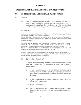
Chapter 7 MECHNICAL VENTILATION AND SMOKE CONTROL SYSTEMS 7.1. AIR-CONDITIONING & MECHANICAL VENTILATION SYSTEMS General (a) Where air-conditioning system is provided in lieu of mechanical ventilation system during emergency, all the requirements specified in this Code for the mechanical ventilation system shall apply to the air-conditioning system. (No illustration) The term “air conditioning” has been defined by the American Society of Heating, Refrigerating, and Air Conditioning Engineers as: “Air conditioning is the process of treating air so as to control simultaneously its temperature, humidity, cleanliness and distribution to meet the requirements of the conditioned space” The use of air conditioning and mechanical ventilation systems will invariably, except for self-contained units, involve some use of pipe works for refrigerant/water circulation and ducts for air distribution and extraction. The use of ducts present the inherent possibility of spreading fire, heat, gases and smoke throughout the building or the floors/areas served. Where air conditioning system is designed to operate during fire emergency, it is to be emphasized that the system shall comply with all the relevant requirements for the mechanical ventilation system in this Code. (b) Construction of ductwork Ducts for air-conditioning and mechanical ventilation systems shall be constructed in compliance with the following requirements: (i) All air-conditioning or other ventilation ducts including framing thereof, shall be constructed of steel, aluminium, glass-fibre batt or mineral-wool batt or other approved material. (ii) All air-conditioning or other ventilation ducts shall be adequately supported. Duct linings & coverings (iii) Duct covering and lining should be non-combustible. However, if it is necessary to use combustible material, it shall:- 7.1.1 1
* when tested in accordance with methods specified in this Code, have a surface flame spread rating of not lower than Class 1, but in areas of building where Class 0 flame spreading rating is required for the ceiling construction under this Code, a Class 0 rating for the covering and lining materials shall be required; * when involved in fire generate a minimum amount of smoke and toxic gases; and * be at least 1.0m away from a fire damper. Flexible joint and connection (iv) Materials and installation of all flexible joints and connections shall be in accordance with SS CP 13 Code of Practice for Mechanical Ventilation and Air- conditioning in Buildings. Diagram 7.1.1(b) Minimum Class 1 for insulation material/barrier lining and adhesives. Where ceiling construction requires class 0, covering and lining insulation material shall also be class 0. Where combustible material is used for the insulation of the duct, it shall be kept at least 1000mm away from a fire damper in order to prevent premature closing of the damper arising from a fire from the combustible insulation material. For flexible joints and connections which are combustible, there is a need to limit the length of the joints and connection to max. 250mm and 400mm respectively. Please see clause 1.2.35 in Volume 1 for illustration. (c) Pipework insulation Insulation for pipework associated with the air-conditioning and mechanical ventilation systems shall comply with the following requirements: 2
(i) Insulation material for pipework together with vapour barrier lining and adhesives shall when tested in accordance with the methods specified in this Code, have a surface flame spread of not lower than Class 1 but in areas of buildings where Class 0 flame spread is required for the ceiling construction under this Code, a Class 0 rating for the insulation material shall be required. Plastic and foam rubber insulation (ii) Notwithstanding the requirements of sub-clause (c)(i), the use of plastic and foam rubber insulation materials of a lower classification may be permissible if: * the material is the self-extinguishing type to the satisfaction of the Relevant Authority; * the insulation material is covered by or encased in a metal sheath or non-combustible cladding materials acceptable to the Relevant Authority. provided that any opening in the element of structure or other part of a building penetrated by the pipework shall be effectively fire-stopped by replacement of the insulation material at the junction of penetration with fire resistant material having equal fire rating. Fire rated proprietary pipework system may be used if it is tested in the manner acceptable to the Relevant Authority. hybrid plaster or other Diagram 7.1.1(c) - 1 3
Diagram 7.1.1(c) - 2 Minimum class 1 for insulation material/barrier lining and adhesives. Where ceiling construction requires class 0, insulation material shall also be class 0. However, the use of 10mm to 15mm maximum diameter pipe works for split unit system would be considered as acceptable. The use of fire collar shall be appropriate for the diameter of the PVC/UPVC pipe and shall be duly secured to the surface of the wall or floor with steel anchor bolts. See Table 3.9A of the fire code for the maximum nominal internal diameter of pipes. (d) Duct enclosure Enclosure of ducts shall comply with the requirements in sub-clause 3.8.9(a). (No illustration) 4
A protected shaft used for the enclosure of services shall comply with the following: (a) The protecting structure for protected shaft containing kitchen exhaust duct and mechanical ventilation ducts serving areas specified in Cl. 5.2.1(g)(i) to (iii) and (h) which pass through one or more floor slabs shall be constructed masonry. Such shaft shall be completely compartmented from the rest of the shaft space containing other ducts or any other services installations. Therefore, protected shaft containing ducts serving other areas which pass through two or more floor slabs shall be of fire rated material. Note: CL.5.2.1(g) – (i) exit staircases and exit passageway (ii) smoke-stop lobby and fire fighting lobby (iii) areas of refuge within the same building Cl.5.2.1(h) – (i) emergency generator engine driven fire pump (e) Ventilation ducts should not pass through smoke-stop or fire fighting lobby. Where unavoidable, the part of the ventilation duct within the lobby shall be enclosed in construction with fire resistance rating at least equal to that of the elements of structure. Such construction shall be in masonry. If other form of fire resisting construction is used, fire damper shall be fitted where the duct penetrates the lobby enclosure. Ductwork through smoke-stop or fire fighting lobbies 5
Ventilation ducts are routed from The AHU Rooms directly into the office space Diagram 7.1.1(e) - 1 With proper pre-planning, ventilation ducts are routed directly from the AHU rooms to occupancy areas, thus avoiding the routing through the protected lobby. 6
Ventilation ducts are routed along protected lobby Diagram 7.1.1(e) - 2 Ventilation ducts are routed along the Smoke Stop Lobby to serve Class 2 & 3. Routing the ventilation ducts through the fire lift or smoke stop lobbies should be avoided. “Unavoidable situations” where ventilation ducts were routed through the fire lift or smoke stop lobbies referred to existing building where physical constraints existed making it difficult to route the ventilation duct through other spaces other than the lobby area. Diagram 7.1.1(e) - 3 7
In addition to providing fire rated enclosure to the duct within the lobby, fire damper is fitted where the duct penetrates the lobby enclosure. Should a fire penetrates the fire damper, it still be contained within the duct. The omission of fire damper to the duct where it penetrates the lobby enclosure is acceptable if a masonry slab is constructed below the duct to act as compartment ceiling. The masonry slab over the lobby completes the compartmentation, thus making the lobby a safe area. (f) Plenum A concealed space between the ceiling and floor above it, ceiling and roof, or raised floor and structural floor of a building may be used as a plenum provided that- (i) The concealed space contains only: * mineral-insulated aluminium-sheathed cable, copper-sheathed cable, rigid metal conduit, enclosed metal trunking, flexible metal conduit, liquid-tight flexible metal conduit in lengths not more than 2 m, or metal-clad cables; * electric equipment that is permitted within the concealed spaces of such structures if the wiring materials, including fixtures, are suitable for the expected ambient temperature to which they will be subjected; metal-sheathed cable, 8
* other ventilation ducts complying with sub-cl. (b); * communication cables television, telephone and inter-communication system; * fire protection installations; * pipes of non-combustible material conveying non-flammable liquids. The supports for the ceiling membrane are of non-combustible material. for computers, (ii) Diagram 7.1.1(f) -1 9
Diagram 7.1.1(f) -2 A fire occuring in the conceal space would be difficult to detect. The smoke and heat could quickly spread beyond the origin of fire in the concealed space. To restrict the unseen spread of smoke and heat in concealed spaces, additional fire safety requirements are imposed under f(I) and (ii). (g) Separating walls No air conditioning or ventilation ducts shall penetrate separating walls. 10
Diagram 7.1.1(g) In terraced child-care centre development, the separating walls are also compartment walls, hence, there should be no sharing of air-con ducts. In sprinkler protected commercial complexes where commercial schools/clinics are located, the separating wall that separates one unit from another is not treated as compartment wall, as such, the requirement that air-con duct should not penetrate the separating wall should not apply. (h) Fire Dampers (i) Provision of Fire Dampers Ventilation ducts which pass directly through a compartment wall or compartment floor shall comply with the following - * where the ventilation duct does not form a protected shaft or is not contained within a protecting structure, the duct shall be fitted with a fire damper where compartment wall or compartment floor; it passes through the 11
* where the ventilation duct forms a protected shaft or is contained within a protecting structure, the duct shall be fitted with fire dampers at the inlets to the shaft and outlets from it. Diagram 7.1.1(I) - 1 Exposed ventilation duct is not fire rated. Fire damper is provided where it passes through the compartment floor or wall to prevent fire spread from compartment to compartment via the duct. Exposed ventilation duct located outdoor shall be weather proof type. Fire rating the duct is not required 12
Ventilation duct contained Within protected shaft Ventilation duct forms A protected shaft Diagram 7.1.1(I) - 2 To prevent fire spread from compartment to compartment via the duct, fire damper shall be provided at the inlets to the exhaust air shaft and outlets from supply air shaft. The dampers shall be properly secured to the protecting structure or protected shaft to prevent any displacement. Fire dampers are provided to inlets of exhaust air shafts and outlets of supply air shaft Diagram 7.1.1(I) - 3 13
(ii) Provision of fire dampers not required Conditions under which fire dampers are not required to be fitted in openings of compartment walls and floors shall be in accordance with SS CP 13 Code of Practice for Mechanical Ventilation and Air-conditioning in Buildings. Clause 6.4.5.3 of SS CP 13 allows the omission of fire dampers at openings in fire resisting walls when: (a) the opening has a horizontal supply branch duct passing through it and has a cross sectional area not greater than 0.02m² and is located at a height not greater than 1.2m above floor level and at distance not less than 6m from other similar unprotected opening; and (b) the opening is located at the wall of a return-air shaft which is fire rated and maintained at a negative pressure at all times and that air is discharged into the shaft through a sub duct of non-combustible material. Diagram 7.1.1(h)(ii) A subduct is an entry piece intended to prevent back flow (venturi effect) of air or products of combustion into non-fire affected compartments. It shall be manufactured from steel of 2mm minimum thickness or be otherwise constructed to have the same fire resistance rating as that required for the shaft. 14
An acceptable alternative material is reinforced concrete integral with the reinforced concrete shaft. If the above designs are to be adopted, QPs shall comply fully with the requirements listed under CL.6.4.5.3 of SS CP 13 and full details shall be given on plan for approval. Prohibition of fire dampers Fire dampers shall not be fitted in the following locations: * openings in walls of a smoke extract shaft or return air shaft which also serves as a smoke extract shaft; * openings in walls of a protected shaft when the openings have a kitchen exhaust duct passing through it; or * anywhere in an air pressurising system; * where explicitly prohibited in this Code. (iii) Diagram 7.1.1(h)(iii) Fire dampers shall not be fitted in any of the smoke extract shaft. The smoke purging system would not be able to function effectively as the fire dampers when subjected to high temperature would close. Smoke purging system is not intended for escape purposes but for dilution of smoke. Hence, there is no need to fire rate the duct works. Fire dampers shall not be provided in the following locations: a)openings in walls of a protected shaft if such openings have a kitchen exhaust duct passing through them; b)anywhere in the supply duct work of air pressurising system to exit staircase; and anywhere in the supply and exhaust ducts serving fire pump room, generator room, fire command centre and flammable store. 15
Where a fire damper is required by this Code to be installed in the airconditioning and mechanical system, its type, details of installation, accessories, inspection door, accordance with SS CP 13 Code of Practice for Mechanical Ventilation Buildings. Construction of the fire damper shall comply with requirements in SS 333 Specifications of Fire Dampers. (No illustration) Fire resisting floor-ceiling and roof-ceiling (i) The space above a suspended ceiling which forms part of a fire-rated floor ceiling or roof-ceiling construction shall not contain ducting incorporated in a prototype that qualified for the required fire-resistance rating, in which case the ducting shall be identical to that incorporated in the tested prototype. Ducting above fire rated ceiling or roof ceiling construction (iv) connection etc. shall of in be and Air-conditioning in (i) unless ducting was Diagram 7.1.1(i) - 1 Diagram 7.1.1(i) – 2 16
Mechanical ventilation ducts are not permitted to be located in the concealed space of fire rated floor ceiling or roof ceiling assembly, unless such ducts are included in the prototype that was tested for the required fire resistance rating. The type of ducting within such ceiling or roof spaces as well as details of openings in such ceiling shall be identical to that incorporated in the tested prototype. * * * Diagram 7.1.1(ii) Area of opening to be protected by fire damper shall not be greater or larger than that in the prototype test panel. Total area of openings in the ceiling to each compartment shall not be greater than that of the prototype test panel. The opening for fire damper may be relocated provided the proximity to structural member (a and b) eg. column, beams and structural walls is not less than that in the prototype test panel. During a fire, the radiant heat from the fire damper would affect the performance of the structural members eg. I-beam in the ceiling space. Hence, the distance between any opening to any structural member shall not be less than that in the prototype test panel. 7.1.1(j) (ii) Openings in the ceiling, including openings to enable the ceiling to be used as a plenum, shall be protected by fire dampers identical to those used in the tested prototype and such openings in the ceiling shall be so arranged that - * No opening is greater corresponding in the prototype test panel; * The aggregate area of the openings per unit ceiling area does not exceed that of the prototype test panel; and in area than that 17
* The proximity of any opening to any structural member is not less than that in the prototype test panel. Diagram 7.1.1(ii) * * * Area of opening to be protected by fire damper shall not be greater or larger than that in the prototype test panel. Total area of openings in the ceiling to each compartment shall not be greater than that of the prototype test panel. The opening for fire damper may be relocated provided the proximity (a and b) to structural member eg. column, beams and structural walls is not less than that in the prototype test panel. During a fire, the radiant heat from the fire damper would affect the performance of the structural members eg. I-beam in the ceiling space. Hence, the distance between any opening to any structural member shall not be less than that in the prototype test panel. * The opening (A & B) may be relocated within the ceiling area provided the proximity to structural member, eg. column, beams and structural walls is not less than that in the prototype test panel. (j) Fire Rated Duct (i) Where proprietary fire rated materials are used to construct the fire rated duct, the fire rating of the fire rated shall have the same period of fire resistance as the wall or floor it penetrates. (ii) Proprietary fire rated duct shall be tested to BS 476 Pt 24 or equivalent and its usage be approved by the Relevant Authority. 18
(iii) Running of non-fire rated duct and/or other building services above the proprietary fire rated duct should be avoided. When unavoidable constraints, the supports to such non-fire rated duct and/or other building services running above the proprietary fire rated duct shall be strengthened such that the tensile stress generated on the supports shall not exceed 10N/mm² and the non-fire rated duct and/or building services shall also be adequately protected to prevent collapse in a fire which will otherwise affect the stability of the proprietary fire rated duct below. due to physical Diagram 7.1.1(j)(iii) (iv) Fans forming part of a fire rated duct shall also be enclosed in the same fire rated enclosure. 7.1.2 (No illustration) Air handling unit room (a) Air handling unit rooms Rooms having no other usage than housing air handling equipment or package units, and their associated electrical controls are not regarded as areas of high risk. However, in situations where the air handling equipment serves more than one compartment, fire dampers shall be provided in air ducts at penetration through the compartment walls and floors to comply with the requirements in Cl.7.1.1(h). 19
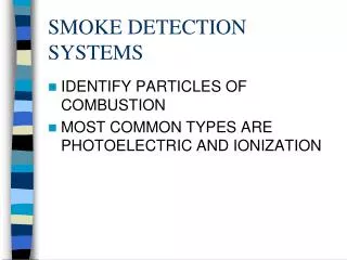
(b) Smoke detectors Smoke detectors of approved type shall be incorporated in the return air stream immediately adjacent to: (i) air handling units serving more than one storey or compartment; or (ii) a single unit in excess of 15000m³/h; or (iii) any AHU as may be required by the Relevant Authority. (c) The function of smoke detectors where required by this code is to initiate action to shut down the AHU automatically when the smoke density in the return-air has become unacceptable for recycling. Details of the requirements shall be in accordance with SS CP 13 Code of Practice for Mechanical Ventilation and Air-conditioning in Buildings. An AHU serving 2 fire compartments Diagram 7.1.2 - 1 20
Air duct penetrating a compartment wall being fitted with a fire damper Diagram 7.1.2 - 2 To prevent the spread of smoke and flame from one fire compartment to another served by a single AHU, smoke detector shall be incorporated in the return air stream adjacent to air handling unit. The smoke detector is to initiate action to shut down the AHU automatically when smoke is drawn into return air system. The fire damper located in the fire compartment wall or floor where the air duct penetrated would only be activated by a fire in any of the compartment. The closing of the fire damper would prevent the spread of fire and, to some extent, the spread of smoke from one compartment to another. Exits (a) Protected shaft of exits, smoke-stop lobbies, including its concealed space shall not be used for supply, exhaust or return air plenum of air handling systems. 7.1.3 21
Diagram 7.1.3(a) The protection of these spaces as means of escape is important. They must not be used as air plenum by other systems. (b) Exit staircase and internal exit passageway Mechanical ventilation system for each exit staircase and internal exit passageway, if provided, shall be an independent system of supply mode only exclusive to the particular staircase, and it shall comply with the following requirements: (i) Supply air for the system shall be drawn directly from the external, with intake point not less than 5 m from any exhaust discharge openings. (ii) For exit staircase serving more than 4 storeys, supply air shall be conveyed via a vertical duct extending throughout the staircase height and discharging from outlets distributed at alternate floor. 22
Diagram 7.1.3(b)(i) There is a need to separate supply air fan from the exhaust louvres by at least 5m measured from the edge of the exhaust louvres housing. This is to prevent the possibility of smoke being drawn into the supply air shaft. For maintaining uniformity of air distribution in the staircase it would be desirable to place the supply air outlet at every floor level, but should not be more than alternate floors. The supply air system to the staircase shall be an independent system as it is expected to operate during emergency to provide smoke free environment to serve occupants evacuating in the staircase. Where the supply air duct serving the exit staircase has to penetrate the staircase enclosure, the portion of the duct where it traverses outside the staircase shall be enclosed in masonry construction or drywall complying with cl. 3.8.7(c) of at least the same fire resistance as the element of structure and it shall not be fitted with fire dampers. (iii) 23
Diagram 7.1.3(b)(iii) The supply air duct is considered as part of the exit staircase, as such that part of the duct, which traverses outside, shall be protected with masonry. As exit staircase is the means of escape, protecting it with masonry would ensure the durability of the shaft during fire situation. As far as possible, the supply air duct should be located within the protected shaft, unless it is unavoidable. 7.1.4 Mechanical ventilated smoke-stop lobby and fire fighting lobby Mechanical ventilation system for smoke-stop lobbies and fire fighting lobbies shall be a system exclusive to these lobbies, and it shall comply with the following requirements: (a) The ventilation system shall be of supply mode only of not less than 10 air changes per hour. (b) Supply air shall be drawn directly from the external with intake point not less than 5m from any exhaust discharge or openings for natural ventilation. (c) Any part of the supply duct running outside the smoke-stop or fire fighting lobby which it serves shall either be enclosed or constructed to give a fire resistance rating of at least 1 hr. 24
The Relevant Authority may at its discretion require a higher fire resistance rating if the duct passes through an area of high fire risk. The mechanical ventilation system shall be automatically activated by the building fire alarm system. In addition, a remote manual start-stop switch shall be made available to firemen at the fire command centre, or at the fire indicating board where there is no fire command centre. Visual indication of the operation status of the mechanical ventilation system shall be provided. (d) Diagram 7.1.4(c) The above diagram shows that the supply air duct to the smoke stop lobbies or fire fighting lobbies is provided with fire damper where it penetrates the compartment wall of the lobby. This is to ensure that the floor to floor compartmentation is maintained. The portion of the duct which traverse outside the protected shaft is enclosed in fire rated construction e.g. fire rated boards. The main purposes of locating the manual start/stop switch with visual indication at the fire command centre, or at the main fire indicating board (FIB) where there is no fire command centre are: a)to allow fire fighting personnel to shut down the supply air system temporarily in the event that smoke is being drawn into the lobby through the outdoor air intake; and b)to allow fire fighting personnel to activate the supply air system should the fire alarm system fail to automatically activate the supply air system. 25
7.1.5 Engine driven fire pump and generator Where mechanical ventilation is installed to provide air for the operation of the following equipment, such system shall be independent of each other and any other system serving other parts of the building: -engine driven fire pump; -emergency generator; (a) Supply air shall be drawn directly from the external and its intake point shall not be less than 5 m from any exhaust discharge openings. Exhaust discharge shall also be direct to the external and shall not be less than 5 m from any air intake openings. Diagram 7.1.5(a) The 5m clearance between supply and exhaust units refers to the horizontal distance. This is to prevent the recycling of exhaust air back into the building. (b) Where the corresponding ducts run outside the room they shall either be enclosed in a structure or be constructed to give at least the same fire rating as the room which they serve or that of the room through which they traverse, whichever is higher. The rating shall apply to fire exposure from both internal and external of the duct or structure. Where the duct risers are required to be enclosed in a masonry shaft, they shall be compartmented from the rest of the shaft space containing other ducts or services installations. 26
(c) No fire damper shall be fitted in either supply or exhaust duct required under this clause. Diagram 7.1.5(b) -1 The above diagram shows that the ducts that run outside the protected masonry shaft are enclosed in a structure or be constructed to give the necessary fire resistance rating. However, for the riser ducts which pass through one or more floors they are required to be enclosed in masonry shaft as required under Cl.3.8.9. This is to ensure that the riser ducts are properly protected within a masonry shaft. The masonry enclosure is a better assurance for integrity and stability than lightweight protection for ducts which pass through floor to floor. The riser ducts, which pass through one floor, mean passing through two floor slabs. Diagram 7.1.5(b) - 2 27
As the mechanical ventilation system to generator room and fire pump room is independent of each other, the riser duct for each system shall be separately enclosed in a masonry shaft and compartmented from the rest of the shaft space containing other ducts or service installations. (d) Duct serving areas other than rooms housing equipment stated in this clause shall not pass through such rooms. Diagram 7.1.5(d) Ducts serving other areas shall not pass through the fire pump room, generator room and fire command centre. The above diagram shows that the ventilation duct is diverted to avoid traversing the aforesaid rooms. Fire command centre Where mechanical ventilation is required for the fire command centre, such system shall be independent of each other and any other system serving other parts of the building. It shall also comply with the following requirements: (a) Supply air shall be drawn directly from the external and its intake point shall not be less than 5m from any exhaust discharge openings. Exhaust discharge shall also be direct to the external and shall not be less than 5m from any air intake openings. (b) Where the corresponding ducts run outside the fire command centre, they shall either be enclosed in a structure or be constructed to give at least the same fire rating as the room which they serve or that of the room through which they traverse, whichever is higher. Where the duct risers are required to be enclosed in a masonry shaft, they shall be compartmented from the rest of the shaft space containing other ducts or services installations. 7.1.6 28
(c) No fire damper shall be fitted in either supply or exhaust duct required under this Clause. (d) Duct serving areas other than the fire command centre shall not pass through the room. For illustration of the above see Cl.7.1.5(a) to (d) 7.1.7 Kitchen (a) Mechanical exhaust system for the cooking area of a kitchen in a hotel, restaurant, coffee house or the like shall be independent of those serving other parts of the building. It shall also comply with the following requirements: (i) The hood and ducts for the exhaust shall have a clearance of 500mm from unprotected combustible materials; Diagram 7.1.7(a)(I) The hood and duct should be separated from other combustible materials by a minimum horizontal clearance of 500mm to prevent ignition through heat radiation. (ii) The exhaust shall be discharged directly to the external and shall not be less than 5m from any air intake openings; 29
The exhaust duct where it runs outside the kitchen shall either be enclosed in a structure or be constructed to give at least the same fire rating as the kitchen or that of the room through which it traverses, whichever is higher. The rating shall apply to fire exposure from both internal and external of the duct or structure. Where the duct riser is required to be enclosed in a protected shaft constructed of masonry or drywall complying with Cl.3.8.9(a), it shall be compartmented from the rest of the shaft space containing installations; and (iii) other ducts or services (iv) No fire damper shall be fitted in kitchen exhaust ducts. Diagram 7.1.7(a) – 1 Diagram 7.1.7(a) - 2 Horizontal run of the exhaust duct outside the kitchen shall be fire rated with minimum 1 hour fire resistance rating. The 1 hour fire resistance shall be applicable to the inside and outside of the duct. The capacity of exhaust fan shall be in accordance with CP13. 30
Diagram 7.1.7(a) - 3 The protecting structure for protected shaft containing kitchen exhaust duct that pass through more than one or more floors shall be of masonry construction. To eliminate the risk of fire spreading from one compartment to another through burning grease within the duct system, a separate exhaust system is required for each hood located in separate compartments. Fire dampers are not permitted within the duct system. The effectiveness of fire dampers is questionable as accumulation of grease would jam the operation of the fire damper and the grease on the downstream side would likely ignite before the fire damper closes. There is also the possibility of false operation and closure other than in a fire situation that could have serious consequences. In any case, the continued running of the exhaust system during a fire involving the cooking equipment or in the compartment would not aggravate the situation. Rooms involving use of Flammable and Explosive Substances (a) Mechanical ventilation system where required for rooms which involve the use of flammable and explosive substances shall be independent from those serving other parts of the building. It shall comply with the following requirements: (i) Ventilation system shall consist of exhaust and supply part with a rate of 20 air-change per hour or any other rates acceptable to the Relevant Authority. The exhaust shall be direct to the external and shall not be less than 5m from any air intake openings; (ii) Where such ducts run outside the room they shall either be enclosed in a structure or be constructed to give at least the same fire rating as the room which they serve or that of the room through which they traverse, whichever is higher. The rating shall apply to fire exposure from both internal and external of the duct or structure. Where the 7.1.8 31
duct risers are required to be enclosed in a masonry shaft, they shall be compartmented from the rest of the shaft space containing other ducts or services installations; (iii) No fire damper shall be fitted in either supply or exhaust duct required under this Clause; and (iv) Duct serving other areas shall not pass through rooms involving use of flammable and explosive substances. Diagram 7.1.8 - 1 The exhaust system (without fire damper) is required to operate efficiently to remove any gaseous or flammable vapour from the room. Flammable/explosive materials shall not be kept or stored in the building. Small quantity of diesel oil (700 litres) would be permissible in generator room (a) Where the flammable vapour being removed is heavier than air, (i) at least one air outlet shall be located at a point near a wall, and no higher than 300mm from the floor, and (ii) at least one air inlet shall be located near the opposite wall, no lower than 300mm from the ceiling. (b) Where the flammable vapour being removed is lighter than air, (i) At least one air inlet shall be located at a point near a wall, and no higher than 300mm from the floor, and (ii) At least one air outlet shall be located near the opposite wall, no lower than 300mm from the ceiling. 32
Diagram 7.1.8 - 2 The flammable vapour is heavier than the air will be discharged via the exhaust system (without damper) as shown above. 7.2 7.2.1 PRESSURISATION FOR EXIT STAIRCASES (a) General In any building of which the habitable height exceeds 24m, any internal exit staircases without provision for natural ventilation shall be pressurised to comply with the requirements in this Code (b) Basement In a building comprising more than 4 basement storeys, exit staircase connected to fire fighting lobby in basement storeys shall be pressurised to comply with the requirements in this Code. (c) Smoke-stop lobby Pressurisation may be extended to smoke-stop lobby provided the pressurisation level complies with Cl.7.2.2(b). 33
Building exceeding 24m in habitable height Diagram 7.2.1 - 1 Exit staircase (B) is pressurised as it is located within the floor space where natural ventilation can not be provided. Exit staircase (C), which is designed without provision for natural ventilation is pressurised. Please note that under clause 2.2.13(c), smoke stop lobby is required to be provided to all staircases, serving building (purpose Group III) exceeding 4 storeys. 34
Diagram 7.2.1 - 7 The above clause specifies that all internal staircases without provision for natural ventilation of building having more than 24m in habitable height, shall be provided with pressurisation notwithstanding that smoke stop lobby is provided. Smoke stop lobby if mechanical ventilated is to be provided with supply air of at least 10 air change per hour during fire mode. There shall be no exhaust duct extracting air out from the smoke stop lobby. The need of a dedicated pressurisation system for each exit staircase is to prevent failure of one system affecting all exits. Air supply to the exit staircase must be obtained from outside the building to minimise the risk of contamination from smoke resulting from a fire in the building. Ductwork associated with the discharge of air throughout the staircase may be located within the staircase itself, otherwise it must be protected in a masonry shaft. To achieve the required air flow velocity on any storey, air supplied by the system should be evenly distributed throughout the height of the staircase by ductwork with outlets not located more than two storeys apart. Relief air grilles (pressure relief dampers) could be used for pressure control thereby minimising periods of excessive force to open doors of the staircases. Variable speed fans with pressure relief damper can be accepted as alternative arrangement. 35
Diagram 7.2.1 -8 Staircase A and transfer staircase A1 is considered as one single staircase sharing a common protected shaft. As staircase A is an internal staircase without openings for natural ventilation, exceeding a habitable height of 24m, it is required to be provided with M/V and pressurisation. Since, staircase A1 is acting as a transfer staircase, it shall likewise be M/V and pressurised notwithstanding the fact it can be naturally ventilated through external openings. The transfer exit passageway which connects staircases A and A1 should also be M/V and pressurised. It is not acceptable to have partial pressurisation to staircase A by introducing a door across the transfer passageway, such that staircase A1 is separated for the provision of natural ventilation. The reason is that by providing a door across the transfer passageway, it would impede the movement of occupants moving towards staircase A1. In this way, the evacuation process within the whole shaft of staircase A would be slowed down. Diagram 7.2.1 - 9 In a building comprising more than 4 basement storeys, the exit staircase designated as fire fighting staircase shall be pressurised. 36
Diagram 7.2.1 - 10 Owing to different in ground levels, staircase B is serving more than 4 basements and is therefore designated as a fire fighting staircase complemented with a fire fighting lobby at each storey. Pressurisation Level (a) When in operation, the pressurisation system shall maintain a pressure differential of not less than 50 pa between the pressurised exit staircase and the occupied area when all doors are closed. (b) Where a pressurisation system is extended to the smoke stop lobby, the pressure gradient shall be such that the pressure at the exit staircase shall always be higher. (c) The force required to open any door against the combined resistance of the pressurising air and the automatic door- closing mechanism shall not exceed 110 N at the door handle. 7.2.2 37
(a) Maintaining pressure differential Diagram 7.2.2(a) (b) Pressure gradient Diagram 7.2.2(b) Where the smoke stop lobby is pressurised, the pressure gradient shall be such that the pressure at the exit staircase is always higher. 38
(c) Force required to open door Diagram 7.2.2(c) Measurement of the force required to open a stair door can be simply carried out by using a force-measuring in the push or pull mode eg. a spring balance. The maximum force permitted to open a door in accordance with this Code is 110 N. This equates to a force of 11.2 kilograms. Lever operated latch sets are probably the easiest to measure. Simply hook the spring balance over the lever handle and depress same to unlatch the door, whilst taking care not to exert any push/pull force in doing so. To take a reading, slowly and steadily pull the spring balance and read the scale as the door just starts to open. Egress velocity When in operation, the pressurisation system shall maintain an airflow of sufficient velocity through open doors to prevent smoke from entering into the pressurised area. The flow velocity shall be attained when a combination of two doors from any two successive storeys and the main discharge door are fully open. Magnitude of the velocity averaged over the full area of each door opening shall not be less than 1.0m/s. 7.2.3 39
Air flow velocity through open door to prevent smoke from entering into the pressurised staircase Diagram 7.2.3 - 1 Diagram 7.2.3 - 2 The air flow velocity measurement through an open door of a pressurised staircase is taken from the entrance of any of two successive doors held open together with its exiting door at the 1st storey. The resulting value of its airflow velocity through the open door shall not be less than 1m/s. 40
Tests conducted by the Commonwealth Scientific and Industrial Research Organization (CSIRO) have demonstrated that air flows in excess of 0.8m/s through a door will minimise the spread of smoke against the direction of flow. A minimum air flow rate of 1m/s has therefore been adopted. This air flow must be maintained across the doorway providing egress from the fire-affected storey into the staircase during a fire. Initially, building occupants from both the fire floor and the floor above the fire floor will evacuate the building and, depending on the fire situation, this may be simultaneous operation. The requirement for two floor doors and the 1st storey door (opening into the exterior) to be open the same time has two applications : (i) When the fire fighters arrive and use the staircase for fire fighting operations, hose connection to the landing valves located on a floor would be carried out. Initially hose will be run from the floor below up the staircase and onto the fire floor hence a minimum opening of two doors is involved. (ii) All required exit staircases must be usable at the same time as either fire fighters or evacuating occupants will be using any of them to exit at the 1st storey door to the street or external safe open area. Thus the final exit door would remain in the open position at all times. 7.2.4 Leakages (a) The rate of supply of pressurised air to the pressurised areas shall be sufficient to make up for the loss through leakages into the unpressurised surroundings. Adequate relief of leaked air out of the occupied area shall be provided to avoid a pressure build-up in this area. The relief may be in the form of perimeter leakages or purpose- built extraction systems. (b) Leakage paths shown by arrows. Drawing 7.2.4 41
Pressurised air could leak through areas such as gaps around doors, windows, other ventilation openings and other places where air will escape. In the above diagram, pressurised air from the exit staircase leaks into the smoke stop lobby (A1) and occupancy areas (A2 & A3). To avoid a pressure built-up in the occupancy area, adequate measures shall be taken to allow air leakage, e.g. thru windows A4 to A7. A pressure build-up would create difficult in opening the doors to the occupancy area. The following are possible ways in which the escape of pressurizing air can be achieved: (a) by window leakage; (b) by specially provided vents at the building periphery; (c) by the provision of vertical shaft. (d) by mechanically operated extraction. 7.2.5 Distribution of Pressurising Air (a) The number and distribution of injection points for supply of pressurising air to the exit staircase should ensure an even pressure profile complying with Cl.7.2.2. (b) The arrangement of the injection points and the control of the pressurisation system shall be such that when opening of doors or other factors cause significant variations in pressure difference, condition in Cl.7.2.2 should be restored as soon as practicable. 42
Not acceptable Diagram 7.2.5 The above installation is not acceptable as over pressurisation would occur at the upper portion of the staircase. Supply air to the staircase should be well distributed by a vertical supply duct, preferably serving all the levels of the staircase. An example of an arrangement showing good distribution of supply air can be seen in diagram 7.2.6. Equipment (a) All the equipment and the relevant controls associated with the pressurisation system shall be so designed and installed to ensure satisfactory operation in the event of and during a fire. 7.2.6 43
(b) Supply air for pressurisation system shall be drawn directly from the external and its intake shall not be less than 5m from any exhaust discharge openings. (c) The pressurisation system shall be automatically activated by the building fire alarm system. In addition, a remote manual start-stop switch shall be made available to firemen at the fire command centre, or at the fire indicating board where there is no fire command centre. Visual indication of the operation status of the pressurisation system shall be provided. Diagram 7.2.6 The “start-stop” switch is required to be provided in the Fire Command Centre, or FIB where there is no FCC. The rationale is to provide the fire fighters greater ease and better control in operating the supply air fan to the staircase. This arrangement, facilitate the supply air fan to be shut from the designated remote “start-stop" location. The supply air fan can then be restarted anytime when required. 44
7.4 7.4.1 BASEMENT SMOKE CONTROL SYSTEM Scope (a) Where the total aggregate floor area of all basement storeys does not exceed 1900sq m, smoke vents in accordance with Cl.7.4.2 shall be provided. Diagram 7.4.1(a) - 1 Diagram 7.4.1(a) - 2 Total aggregate floor area of basement storeys = Area of institutional Basement 1 & 2) + staircases + services area (TAS, Transformer room etc) + plant/equipment room of basement 1. • If total aggregate area <1900m² (smoke vents shall be provided - see clause 7.4.2). If total aggregate area >1900m² (engineered smoke control system is required), See also clauses 7.4.1(b)(ii) & (iii). 45
(b) Where the total aggregate floor area of all basement storeys exceeds 1900sq m, engineered smoke control system that complies with the requirements stipulated in Cl.7.4.3 shall be provided for all parts of basement with the following exceptions: Exception (i) Where the basement or a portion of the basement is used as carpark, Cl.7.1.9 can be adopted to the carpark provided it is compartmented from rest of the basement; Diagram If the total floor area of basements 1 & 2 (other usage + car park) >1900m², engineered smoke control is required to be provided in the basement storeys; except the car parking areas in basements 1 & 2 which need to be provided with smoke purging system under clause 7.1.9. (ii) Plant/equipment room with floor area not exceeding 250sq m and compartmented from rest of the basement, and provided with two doors for better reach in fire fighting operation. 46
Diagram 7.4.1(b)(ii) Where the plant/equipment room is not greater than 250m², fire fighters can fight a fire in that room from its doorway, If the plant/equipment room is not larger than 100m2, one access door would be considered acceptable. (iii) Plant/equipment room with floor area exceeding 250sq m but not exceeding 1900sq m, smoke vents in accordance with cl.7.4.2 or smoke purging system of at least 9 air-change per hour shall be provided. Diagram 7.4.1(b)(iii) Where floor area of the plant/equipment room is in excess of 250m², but not exceeding 1900m², provision of smoke vents in accordance to Cl.7.4.2 or smoke purging system in accordance with Cl.7.1.9 would be acceptable. Also, for a plant room in excess of 1900m², the provision of either engineered smoke control system or smoke purging system is acceptable. 47
Subclause (iii) is meant to grant relaxation over the general requirement as service rooms are usually of low occupancy load. Common corridors serving multiple plant rooms/service rooms may be pressurised. Common areas outside the plant rooms/service rooms should be provided with engineered smoke control system. Service areas such as laundries, office, storeroom and workshops (restricted to compartmented, smoke venting provision in accordance with Cl.7.4.2 or smoke purging system of at least 9 air-change per hour may be acceptable for those areas in lieu of the engineered smoke control alarm/extinguishing system in accordance with table 6.4A shall be provided where required. Basement Floor Plan 7.4.1 (iv) staff only) which are system, Automatic fire Diagram 7.4.1(iv) The above clause is mainly applicable to hotel building. Service area such as laundries, offices, stores and workshops are restricted to staff only shall be compartmented. The total area of these compartments shall not exceed 1900m². (per storey basis) Each compartment shall be provided with smoke venting or smoke purging system. 48
7.4.2 Smoke vents Smoke vents shall be adequately distributed along perimeter of basement and their outlets shall be easily accessible during fire fighting and rescue operations. Installation shall comply with the following requirements: (a) The number and their sizes shall be such that the aggregate effective vent openings shall not be less than 2-½ per cent of the basement floor area served. (b) The vent outlets if covered under normal conditions shall be openable in case of fire. (c) The position of all vent outlets and the areas they serve shall be suitably indicated adjacent to such outlets. (d) Where ducts are required to connect the vent to outlets, the ducts shall either be enclosed in structure or be constructed to give at least 1 hour fire resistance. (e) Separate ducts and vent outlets shall be provided for each basement storey. Diagram 7.4.2 • Smoke ventilation shafts which are extended through storeys above, shall be enclosed with minimum 1 hour fire resistance Separate smoke ventilation shafts and outlets shall be provided for each basement storey Smoke venting outlets shall be so arranged that a through draught can be created. The outlets shall be evenly and strategically located so that they can serve the general spaces in the basement and not be hidden in room Outlets covered by stalled boards, or approved type pavement lights shall be readily openable/breakable • • • 49
The positions of all smoke vent outlets and the basement level or areas they serve shall be suitably indicated on the external face of the building adjacent to such outlets. Smoke vents and pavement glass blocks serving only one basement storey need not be indicated by signage. 7.4.3 Engineered smoke control Where engineered smoke control system is required, it shall be provided as specificed in Cl.7.6. (No illustration) SMOKE CONTROL SYSTEM A smoke control system specified in Cl.7.6 shall be provided where: (i) The requirements for compartmentation specified in Cl. 3.2.1 and 3.2.4(a) and (b) are relaxed under the conditions in Cl. 3.2.6 for `Atrium spaces' in a building; and (ii) The total floor area of any compartment in a building or part of a building exceeds 5000 sq.m. 7.5 7.5.1 Smoke control system Diagram 7.5.1 50