Download
1 / 27
290 likes | 572 Views
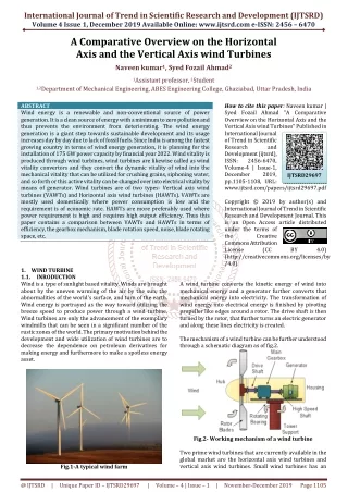
The Low-Cost Vertical Axis Wind Turbine Project- An Exercise in Learning Across Disciplines. Akshay Pendharkar and Narayanan Komerath Daniel Guggenheim School of Aerospace Engineering Georgia Institute of Technology . Acknowledgements.

E N D
The Low-Cost Vertical Axis Wind Turbine Project- An Exercise in Learning Across Disciplines AkshayPendharkar and Narayanan Komerath Daniel Guggenheim School of Aerospace Engineering Georgia Institute of Technology
Acknowledgements This work was supported under a NASA grant monitored by Mr. Tony Springer. The authors are also grateful for the help of Mr. James Steinberg of the School of Electrical and Computer Engineering at Georgia Tech, who assisted in developing the charging circuit.
Conclusions • This case study documents the multi-year process by which a small device is developed using a team of mostly undergraduates. • The detailed process exhibits several positive and negative features of the constantly changing team. • Agreat deal of the effort goes into the students' learning, as is appropriate for our environment. • The particular constraints on the system are driven by the needs of the anticipated customer environment. • These do introduce challenges, as well as exciting possibilities for innovation.
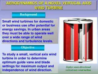
Overview • One of the 5testbedsdeveloped at our Micro Renewable Energy Laboratory. • Low-cost Vertical Axis Wind Turbine (VAWT) R&D testbedaimed to refine analyses, design features and construction techniques for family-use devices. • Multi-year hands-on and analytical project. • Integrates knowledge across disciplines, used to build experience and capabilities. • Paper traces evolution of multi-year project, summarizes recent experience. • Issue • How does an undergraduate team, learn what they need and innovate for success?
Some items developed (b) Rope dynamometer (a) Blade aerodynamics test rig with 1 load cell (c) Starting/control circuitry (d)
Variable-Mass, Constant Bearing Loader for Power Loss Deconstruction (TupperWare Jar With Sand and Weights)
Several Models Bicycle WT, 2006 4-biplane, 3-ft VAWT 6-ft thin-vane VAWT 3-ft, 3-biplane, PVC blades @ 220+rpm 6-ft, composite-blade, Pacific Winter model
Multi-Disciplinary Aspects • Aerodynamics of airfoil sections and finite wings. • Reynolds number dependence, • Optimizing Savoniusdrag tubes for self-starting, • Turbomachinevelocity diagrams to find regions of driving and dragging • Streamtubeinteractions and power extraction effects. • Unsteady aerodynamics in optimal tip speed range of operation. • Convenient platform to introduce physics, Statics and Strength Of Materials: • Needs innovation on using flexible components of unknown strength. • Design and construction of 6-foot turbine: CAD and structural analysis software. • Dynamics and vibrations: Moment of inertia of each component was measured and computed to model the dynamic system. • Vibrations had to be diagnosed and reduced. • Mechanical design and graphics skills refined. • Fabrication of the various parts was done in consultation and iteration with the professional machinists in the Machine Shop. • TupperWare Jar approach for constant bearing load in drag deconstruction
What did they learn? • Composite wing construction technology: proper ways to mix resin and hardener, cutting wood templates, fixing ribs, leading edge and trailing edge pieces, filling foam, laying the fiberglass cloth, covering with the resin mix, curing, sanding with protective equipment and cleanup processes, and verifying the shape and refining it. • Structural testing to validate the predictions from the ANSYS code using improvised rigs. • Smulationdeveloped in MATLAB and FORTRAN. • The motor, generator and associated circuitry. Switching ckt with help of EEC instructor. • Data acquisition and analysis is very hard to fit into the standard curriculum. The VAWT testbed provides a focal point to teach about the Nyquist sampling criteria, Wiener-Khintchine theorem relating frequency domain and time domain statistical quantities, statistical averaging of data, and all other aspects of signal processing. • Figure of Merit approach to system improvement. • Socioeconomic aspects: conceptual models of the end user customers of such systems • Business realities: Why HAWTS and VAWTS are not seen in large numbers or widespread use at the small scale level
Educational Assessment • Assessing student performance: • Independent of success or failure of the device or system. • Grading based on the instructor's understanding the effort and thought invested by student. • But… • Nonlinear effort and student initiative are central to success of many projects. • 3-fold approach: • Weekly Project Document updates plus face-to-face meetings - continual assessment and feedback on the thought and effort and discuss alternative approaches. • Continuity across semesters: Project Document and website. • Project leader is an undergraduate. • Tie grading to initiative and effort, but be strict about regularity and completeness of reporting and meeting attendance. • With good, regular attention and reporting, most students able to earn A grades. • Some don’t. • Ultimately, papers with results have been presented at 3 peer-reviewed professional conferences outside Aerospace Engineering.
Publications • Komerath, N.M., “Prediction and Validation of a Micro Wind Turbine for Family Use”. Proceedings of the IMETI Conference, July 2011 • McGowan, R., Komerath, N.M., Raghav, V., “Vertical Axis Micro Wind Turbine Simulation and Control”. Proceedings of IEEE EPSICON, Trissur, India January 2012 • McGowan, R., Pendharkar, A., Morillas, K., Pinder, M, Komerath, N.M., Optimization of a Vertical Axis Micro Wind Turbine for Low Tip Speed Ratio Operation. Proceedings of the 10th Annual International Energy Conversion Engineering Conference, Atlanta, GA July 2012.
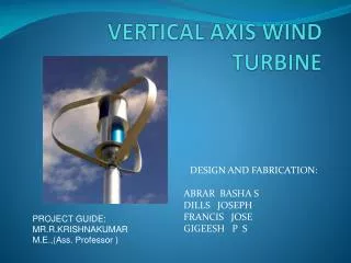
Low Tip Speed Vertical Axis Wind Turbine Aim Objective Optimize design for low tip-speed ratio • Develop micro wind turbine for • single-family use in India • Vertical axis vs. horizontal axis • Local manufacture & maintenance • Lifecycle safety & environment • Technically complex to design! TSR = Blade tip tangential\ Windspeed • Operation at low wind speeds • Low blade tip speed TSR Methods • Aerodynamics simulation validated • Low Reynolds number corrections • Wind tunnel testbed • Azimuthal modification strategy to improve operation • Real-time control options
Project Goal • Determine maximum rpm of VAWT with different components added. • Calculate the moment created from the drag of each new component • Determine CD of each component. • Pinpoint sources of drag, and propose methods to decrease drag. • Decreased drag will lead to higher tip-speed ratio, leading to better efficiency.
Experimental Setup • To accurately analyze drag, we need to keep friction constant on the bearings as we add and remove components. • To keep friction constant, we need to keep weight constant. • We modified a four liter bucket to set on a nut attached to the center axis. • By adding and removing a measured amount of sand, we were able to maintain a constant weight on the bearings, and thus kept friction constant.
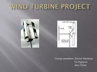
Configurations Tested • The Vertical Axis Wind Turbine (VAWT) has three main component types • Two triangular plates attached to center rod. • Three metal arms attached to each of the triangular plates. • Six blades connecting pairs of arms. • We tested the configurations of center rod only, one triangular plate, both triangular plates, then adding three arms, six arms, then adding three blades, and finally all six blades.
Procedure • Each configuration of the VAWT was tested using a 12 volt system and a 24 volt system. • The VAWT was turned on and allowed to reach a steady max rpm. • The time elapsed for the VAWT to rotate 1 degree was recorded by an encoder. • Once reaching a steady maximum, we averaged a thousand time elapsed readings to calculate the maximum rpm for the configuration.
Sources of Error • When the bucket had a large mass of sand, spinning the bucket with the axis caused the VAWT to vibrate. • The vibrations decreased the maximum RPM achievable. • For this reason, adding triangular plates and removing sand to the bucket actually increased slightly the maximum RPM achievable. • Once we began adding arms, the vibrations went away and no longer affected our data. • Since the triangular plates are small and close to the axis, they have much less drag than the arms and blades. • As our goal is to target sources of drag, we can eliminate these plates as the main source of drag, so our data can still be used to achieve our goal.
Relating RPM and Torque • , where P is the power produced by the battery • For the 12V battery, P = 32.37 W • For the 24V battery, P=129.517W • The motor torque for a given RPM is calculated in the table to the right 24 Volt System 12 Volt System
Arms: Relating Torque to CD • Begin with D = ½ρV2SCD • Drag on a differential area on bar: • dD = 1/2ρV2CDdS • dD = 1/2ρV2CDcdx • Since V=ωx, dD = 1/2ρω2CDcx2dx • Since Drag is perpendicular to the moment arm, M=xD • For a differential drag element: • dM = x*dD = 1/2ρω2CDcx3dx • Integrating along the bar fromx1 to x2 yields: • M = (1/8ρω2CDc)(x24-x14), where x1 and x2 are the distances of the two ends of the bars to the center This uses the CD for all three bars. CD of one bar is 1/3 CD total, so: • M=(3/8ρω2CD, 1 barc)(x24-x14) Top View of a rotating arm ω x dx c Center V
Blade: Relating Torque to CD • Again, begin with the differential drag on a differential blade element: • , where dx lies along blade, c is cord length • Due to circular motion about center: • V=ωr • Based on geometry, R is the fixed arm length: • Relating moment and drag: • Since the blade is tilted 23 degrees from vertical: • Also, we can relate dx and dr by using geometry: Above view of VAWT Note how r vector is not constant along blade 60 BLADE r R θ 60 ARM ARM
Blade Torque Derivation cont. • Substituting yields: • Finally, relating dr and dθ: • Final differential equation: • Integrating θ from 0 to π/6, then multiplying by two to get both halves of the blade, yields: • Again, this is the moment due to all blades for a given configuration. The moment from one blade will be equal to a third or sixth of the total moment depending on the configuration.
Analysis • For both the three blade and six blade systems, the blades contributed much more drag than the bars. • CD for a NACA 0012 should be around 0.1, yet we calculated our blades to have a CDof 0.311, which is three times as high as it should be. • Lowering the CD of the blade would significantly reduce drag. • Making the blade smoother and sturdier could decrease skin-friction drag.