Download
1 / 45
1.21k likes | 3.07k Views
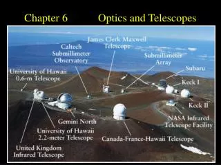
Chapter 6 ELECTRO-OPTICS. refractive index( anisotropic crystal ) change with electric field Phase or Polarization change with refractive index. (1) Electro-optic Effect. Electro-optic material. Light. Electric field. Possible application. Optical scanning device.

E N D
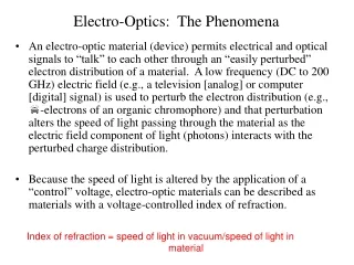
Chapter 6ELECTRO-OPTICS Fundamentals of Photonics
refractive index( anisotropic crystal ) change with electric field Phase or Polarization change with refractive index (1) Electro-optic Effect Electro-optic material Light Electric field Fundamentals of Photonics
Possible application Optical scanning device controllable focal length. analyzer polarizer 0 U U U Polarization modulation Light intensity modulator Phase modulator Fundamentals of Photonics
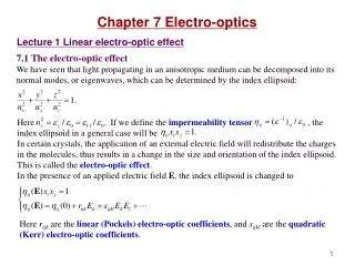
The refractive index of an electro-optic medium is a function n(E) of the applied electric field E. Pockels and Kerr Effects Terms higher than the third can be neglected. Fundamentals of Photonics
Pockels Effect the third term is negligible n(E) r : Pockels coefficient or the linear electro-optic coefficient range: 10-12 to 10-10 m/V n Pockels medium or Pockels cell 0 E (a) Fundamentals of Photonics
Kerr Effects the second term is negligible n(E) : Kerr coefficient or the quadratic electro-optic coefficient. n Range: 10-18 to 10-14 m2/V2 (for crystal) 10-22 to 10-19 m2/V2 (for liquid) Kerr medium or a Kerr cell 0 E (b) Fundamentals of Photonics
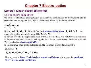
Crystal Optics z k n3 na n2 y n1 nb x (2) Electro-Optics of Anisotropic Media The index ellipsoid 7 Fundamentals of Photonics 2014/11/13
Pockels and Kerr Effects E = (El, E2, E3) {rijk} : linear electro-optic (Pockels) coefficients. E {ijkl} : quadratic electro-optic (Kerr) coefficients. 8 Fundamentals of Photonics 2014/11/13
9 Fundamentals of Photonics 2014/11/13
index ellipsoid equation where ij(0) is a diagonal matrix with elements l/n12, l/n22, and l/n32 principal refractive indicesn1(E), n2(E), and n3(E). 10 Fundamentals of Photonics 2014/11/13
Optic axis z E y x ne no y no x Trigonal 3m Crystals (LiNbO, LiTaO,…) Uniaxial crystal n1= n2 = no, n3 = ne Assuming : E = (0,0, E), z 11 Fundamentals of Photonics 2014/11/13
Optic axis z E y x x2 x’2 x’1 x1 Tetragonal 42m Crystal (e.g., KDP and ADP) 12 Fundamentals of Photonics 2014/11/13
Electra-Optic Modulators and Switches Phase Modulators V L define V: half-wave voltage Fundamentals of Photonics
V d V L V V Traveling-wave transverse modulator Longitudinal modulator Transverse modulator d=L several GHz Fundamentals of Photonics
Electrodes Input light V Waveguide 0 V Modulated light E 0 Cross scction integrated-optical phase modulator Fundamentals of Photonics
Dynamic Wave Retarders phase retardation Polarization light Fundamentals of Photonics
Branch 2 F(V) C 1 Io Ii V Branch 1 B 0.5 A 0 Vn V • Intensity Modulators: Use of a Phase Modulator in an interferometer Fundamentals of Photonics
Input light Ii V 0 Modulated light I0 An integrated-optical intensity modulator (or optical switch). A Mach-Zehnder interferometer and an electro-optic phase modulator are implemented using optical waveguides fabricated from a material such as LiNbO3 Fundamentals of Photonics
Io F(V) 1 B Polarizer 0.5 t 0 V Vn Ii Polarizer t s • Intensity Modulators: Use of a Retarder Between Crossed Polarizers if linear modulation Fundamentals of Photonics
d d - a a -V D q q D +V L L Scanners scan resolution N Beam angular divergence: Large V Fundamentals of Photonics
Electro-optic polarization retator Birefringent crystal position switch based on electro-optic phase retardation and double refraction. Fundamentals of Photonics
Directional Couplers Waveguide 1 PI(0) P1(0) P2(L0) Fibers Waveguide 2 V PI(0) L0 PI(z) d P2(z) P2(L) L0 z 0 (a) power-transfer ratio Fundamentals of Photonics
F 0 =2n/0 : mismatch of the propagation constants V0: switching voltage. C : coupling coefficient. Lo = /2C Fundamentals of Photonics
F 1 0 V0: switching voltage. Lo = /2C C : coupling coefficient. Fundamentals of Photonics
- Incident light + - y Modulated light Modulated light + Transparent electrodes Write iamge IW(x,y) + Mirror Transmittance T(x,y) Electro-optic material y Incident light x Photoconductive material x Spatial Light Modulators Electrically addressed spatial light modulator Photo-addressed spatial light modulator Fundamentals of Photonics
Dichroic reflector of red light Polarizing beamsplitter Transparent electrodes Modulated light White light (blue) BSO Incident read light (red) Pockels readout optical modulator (PROM). Fundamentals of Photonics
z E Electro-optics of Liquid Crystal • Electrical Properties of Nematic Liquid Crystals Optics axis rotate Uniaxial symmetry Anisotropic || (n||,ne ) (n, no ) Fundamentals of Photonics
x x E q d z z y y Liquid crystal cell Phase modulator Fundamentals of Photonics
q (V-Vc)/Vo (V-Vc)/Vo Dependence of the tilt angle q on the normalized rms voltage Dependence of the normalized retardation T/Tmax=[n(q) – n0]/(ne-no) on the normalized rms voltage when n0=1.5, for the values of △n=ne-no indicated. Fundamentals of Photonics
Nematic Liquid-Crystal Retarders and Modulators Phase modulator Polarization modulator Fundamentals of Photonics
x Polarizer Incident light Mirror Reflected light Liquid- crystal cell y s Reflective light intensity modulator =/2 (off state) = 0 (on state) Fundamentals of Photonics
Twisted Nematic Liquid-Crystal Modulators Linear polarization direction rotate with liquid crystal twist direction Fundamentals of Photonics
x (a) Bright y Polarizer Polarizer x (b) Dark s s y Fundamentals of Photonics
Polarizer Mirror Liquid- crystal cell s Reflective twist nematic liquid crystal modulator, normally 45degree twisted Fundamentals of Photonics
x x q q 90° q q q q z z Smectic layers y y Ferroelectric Liquid Crystals Faster response (us, nematic: ms) smectic-C phase Surface stable Ferroelectric liquid crystal (SSFLC), only on-off state Fundamentals of Photonics
Liquid Crystals spatial light modulator Liquid-Crystal Displays • passive devices • relatively slow • optical efficiency is limited because of polarization • the angle of view is limited seven-bar-segment LCD Fundamentals of Photonics
Light-locking layer Dielectric mirror Polarizing beamsplitter Transparent electrodes Modulated light White light Incident read light (red) Liquid crystal Photoconductor Optically Addressed Spatial Light Modulators Hughes liquid-crystal light valve Fundamentals of Photonics
(b) Conduction band (c) (a) Fe3+ Fe2+ x Valence band (d) Electric field Photorefractive materials free charge carriers space-charge distribution light refractive index distribution LiNbO3 Fundamentals of Photonics
Simplified theory of photorefractivity rate of photoionization ND : the number density of donors ND+: the number density of ionized donors S : the photoionization cross section. electrons recombination rate n(x): electrons density , R is a constant In equilibrium, R(x) = G(x), Fundamentals of Photonics
Electric Field e : electron mobility K: Boltzmann’s constant T : temperature. Refractive Index Fundamentals of Photonics
EXAMPLE Incident light If m is small Fundamentals of Photonics
Nonuniform light Nonuniform light I(x) Photoionization Free-carrier density x Diffusion x Fixed-charge density + + Recombination at traps x - E(x) Electric field x △n(x) Refractive index grating x Response of a photorefractive material to a sinusoidal spatial light pattern Fundamentals of Photonics
Wave 1 (reference) Wave 2 (object) Grating Applications of the Photorefractive Effect Two-wave mixing: dynamic holography Fundamentals of Photonics