Download
1 / 7
70 likes | 213 Views
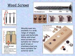
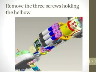
Remove the three screws holding the helbow. Turn the highlighted part until you can see the set screw throught the hole in the yellow part. Note: there are 2 set-screws one upon the other. Remove both. Remove the four screws that hold the yellow part.

E N D
Turn the highlighted part until you can see the set screw throught the hole in the yellow part Note: there are 2 set-screws one upon the other. Remove both.
Remove the four screws that hold the yellow part Now you should be able to separate the RED part fom the YELLOW part. Help yourself with 2 screwdriver or use the holes in the back of the helbow to help forcing out the part (as shown by the arrow).
Now inspect the condition of the blue part (RC_IIT_007_P_015) Especially check that this small flat surface is not damaged or «rounded» Alternatively you can send us a picture like this of your part and we ahould be able to tell what is the state.
Check that the RC_TLR_007_P_003_00 is tighely screwed onto RC_IIT_007_P_015 RC_TLR_007_P_003_00 If they are loose, you can remove this screw, take the two parts apart, apply some thread locker and tighten everything back up RC_IIT_007_P_015
Now inspect the condition of the motor shaft Make sure this flat on the shaft is not damaged Alternatively you can send us a picture like this of your part and we ahould be able to tell what is the state.
Carefully remove the screw that hold the motor and inspect them • These are 2x M1.6x5 countersunk screws. • Use the following precautions: • Replace in any case after removal with like screws. • Do apply some thread lock • DO NOT USE LONGER SCREWS they will damage the motor. • Do not over-tighten these screws, the thread will strip easily • If they are cut or broken most probably we will have to replace the pronosupination motor