1. CASE STUDY - CONTINUOUS OHMIC HEATER Direct ohmic heater with three parallel channels:
PSR experiment. Verification of CFD models. by Stimulus Response method. 1. CASE STUDY - CONTINUOUS OHMIC HEATER Direct ohmic heater with three parallel channels: Reynolds number in central channel 1300, in lateral channel 1600, inlet/outlet pipes 3000.

1. CASE STUDY - CONTINUOUS OHMIC HEATER Direct ohmic heater with three parallel channels:
E N D
Presentation Transcript
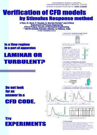
PSR experiment Verification of CFD models by Stimulus Response method 1. CASE STUDY - CONTINUOUS OHMIC HEATER Direct ohmic heater with three parallel channels: Reynolds number in central channel 1300, in lateral channel 1600, inlet/outlet pipes 3000. Acknowledgement:Research is subsidized byInternational Atomic Energy Agency in Vienna (No.: 11557 and by Ministry of Education of Czech Rep. No. J04/98: 212200008 Is a flow regime in a part of apparatus 2. EXPERIMENTS Radiotracer Tc99m was injected into inlet pipe. Local responses were detected by collimated scintillation detectors D1, D2, D3 and D4 (see Fig). RTD (residence time distribution) of the heater was determined by stimulus response method using the conductivity probes C1 and C2 measuring KCl concentration at inlet and outlet: LAMINAR OR TURBULENT? 3. CFD MODEL and RESPONSE EVALUATION CFD model (Fluent 5.2, laminar, k-, RNG and low Reynolds flow models) predicts distribution of tracer c(t,x,y,z) in time t. While the RTD is given directly by Fluent, the theoretical responses of detectors D1,2,3 and 4 must be calculated according to : where D(x,y,z) is the response of collimated detector to the unite activity situated in x,y,z (PSR-Point Source Response). The function D(x,y,z) can be evaluated theoretically (using view factor/ Monte Carlo method) or by interpolation of values D(xk,yk,zk) determined experimentally (the locations xk,yk,zk of unit activity tracer have nothing to do with position of CFD nodes) : lk is distance between (x,y,z) and (xk,yk,zk) points. J.Thýn, M. Nový, P. Houdek, G. Borroto Portela*) and R.Žitný Department of Process Engineering CTU in Prague, Faculty of Mechanical Engineering, *) ISCTN Avenida Salvador Allende, La Habana, Cuba E-mail: thyn@fsid.cvut.cz Do not look 4. COMPARISON of EXPERIMENT WITH CFD PREDICTION for an answer in a CFD CODE. Local responses of collimated detectors: Experimental response (1), RNG k- model (2) and laminar flow (3) Comparison of RTD: CFD prediction and conductivity method Try • 5. CONCLUSIONS: • New method of CFD postprocessing enables prediction of collimated detector responses to a gamma radiation tracer distribution. • A case study predicts only small difference between the laminar and turbulent flow model with small advantage for RNG k-. An effect of real injection, inaccuracy of collimation algorithms as well as effects of operational parameter ambiguities are to be analysed in future. EXPERIMENTS