ENG2000 Chapter 7 Beams
ENG2000 Chapter 7 Beams. Overview. In this chapter, we consider the stresses and moments present in loaded beams shear stress and bending moment diagrams We will also look at what happens when a beam is deformed in terms of the axial stress in the deformed beam

ENG2000 Chapter 7 Beams
E N D
Presentation Transcript
Overview • In this chapter, we consider the stresses and moments present in loaded beams • shear stress and bending moment diagrams • We will also look at what happens when a beam is deformed • in terms of the axial stress in the deformed beam • and the flexural rigidity of a beam • The chapter will finish by considering the failure of a column due to an axial compressive force • buckling
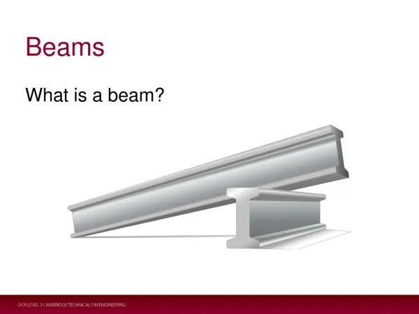
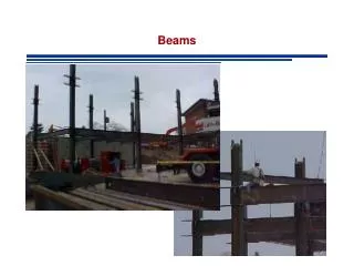
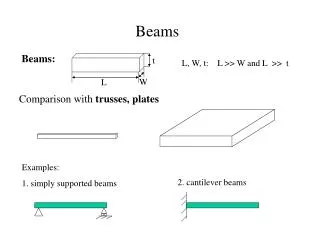
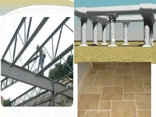
Beams with concentrated loads • A beam is defined as a slender structural member • For trusses we assumed that what happened in the members was unimportant to the system • although the nature of the members clearly affects the strength of a truss • here we look at what happens when beams are loaded • We will look at the internal forces – axial and shear – and moments in the loaded beam • Three types of beam are statically determinate …
simply supported beam cantilever beam combination beam
Cantilever Free body diagram of the cantilever
If we cut the beam at an arbitrary point, we can determine the system of forces and moments required to maintain equilibrium This system must include axial, shear and moment
Shear force & bending moment diagrams • In order to determine whether the beam can support the loads required, we need to determine the distribution of stress in the beam • i.e. P, V, and M as a function of x • Let’s take the following example: • we first cut the beam at an arbitrarylocation between the left end andthe force • and then the other side of the force
For 2L/3 < x < L • P = 0 • V = - 2F/3 • M = (2F/3)(L - x) • For 0 < x < 2L/3 • P = 0 • V = F/3 • M = Fx/3
General equations • For a generalised distributed load of w(x) N/m: (no axial force) (shear increases with x) (moment = shear x distance)
Stresses in beams • A simple beam, such as this firewood, snaps when a moment is applied to each end • Similarly, structural members can deform or fail due to bending moments • This will allow us to calculate the distribution of axial stress
Geometry of deformation • We will consider the deformation of an ideal, isotropic prismatic beam • the cross section is symmetric about y-axis • All parts of the beam that were originally aligned with the longitudinal axis bend into circular arcs • plane sections of the beam remain plane and perpendicular to the beam’s curved axis Note: we will take these directions for M0 to be positive. However, they are in the opposite direction to our convention (Beam 7), and we must remember to account for this at the end.
Concrete • While we are mostly assuming beams made of steel or other metals, many means are made of concrete • and concrete does not support a tensile stress • For concrete beams, we assume that only the material on the compressive side of the neutral axis actually carries a load http://www.uaf.edu/~asce/failure.jpg
One solution to this is pre-stressed concrete • where metal bars set within the concrete are pre-stressed to provide an initial compression to the concrete beam • so it can withstand some tension, until the pre-stress is overcome The yellow guidelines highlight the camber (upward curvature) of a pre-stressed double T. The pre-stressing strands can be seen protruding from the bottom of the beam, with the larger strands at the bottom edge. The tension is these strands produces the camber, the beam is straight when cast. http://urban.arch.virginia.edu/~km6e/tti/tti-summary/half/concrete1-1-01-detail.jpeg
Expression for stress • If we take a small element of width dx, and deform the beam… • r is the radius of the neutral axis • at y = 0 (neutral axis), dx remains unchanged • dx’ is width at y • Hence we can write a strain • ex = (dx’ - dx)/dx = (dx’/dx) - 1 • Also • dx = rd • dx’ = (r - y)d
Hence • Which tells us that the extension parallel to the beam axis is linearly related to the distance form the neutral axis • and the sign indicates compression for positive y, i.e. below the neutral axis • We can now calculated the stress • assuming no additional loads – just the moment
Hence we can sketch of the stress normal to the axis of the beam …
Location of neutral axis • The previous analysis used r, but did not relate r to the applied moment • and we don’t know where the neutral axis is located either • Imagine that we cut the beam at some point • Since the moment M0 does not exert a net force • the sum total of the stress at the cut section must also be zero
Expressed mathematically • where A is the area of the beam’s cross section • Substituting in for sx, • Recall that the centre of mass is given by • ycom = (∫y dm)/m • For a geometric shape, the equivalent point is the centroid, given by • Hence the neutral axis (at y = 0) passes through the beam’s centroid
Relating stress to applied moment • For the free body diagram of the chopped beam, the sum of moments must also be zero for equilibrium • For an elemental area of the cross section, the moment about the z-axis is – ysxdA • Hence the total moment for the segment is
Using • we find that: • where • I is a very important figure of merit for a beam’s shape, known as the moment of inertia • Hence
Conventional directions • We have to revert to our convention for the positive direction of moments • see Beam 7 and Beam 13 • by letting M = -M0 • Hence, our equations are as follows • Radius of curvature • positive r means the positive y-axis is on the concave side of the neutral axis • EI is known as the flexural rigidity of the beam • Extensional strain • Normal stress
Interpretation of moment of inertia • What does the moment of inertia mean? • and flexural rigidity, EI • Essentially, this says that the beam is stiffer if the material in the beam is located further away from the centroid (neutral axis) • so any area, dA, is more effective at stiffening the beam depending on the square of the distance • hence, if you want to make a strong beam with little material, make sure that the material is as far as possible from the centroid • hence, ‘I’ beams http://www.tricelcorp.com/images/ibeam.jpg
Parallel axis theorem • If we know I for a particular axis, we can calculate the value for a different parallel axis in a straightforward way • where Ix’,y’ are the moments about one set of axes and dx,y are the distances to the new set of axes y’ y A dx x’ dy x
Summary so far • So we can now calculate stresses and moments within a beam, and we know how the beam shape effects the stress • Calculation of the deformed shape of the beam is possible, but beyond the scope of this course • essentially, the ways in which the ends of the beam are ixed determines the deformed shape • by providing boundary conditions to the differential equations relating deformation to load • see chapter 9 of Riley • However, we did say earlier that buckling of long slender beams is also important • which is why we need trusses in the first place
Buckling of columns • Imagine a hacksaw blade • sy = 520Mpa • cross section is 12mm x 0.5mm • so the blade should withstand a compression of 3120N ≈ 300kg • However it is easy to cause the blade to fail
Euler buckling • Buckling is a geometric instability that causes a structural column to fail well before its ultimate load • Let us assume a column has already deformed due to an axial load • and we will determine the force we need to maintain equilibrium • Cutting the beam at an arbitrary point gives us …
Here M = Pv • where v is the beam’s deflection • It turns out that • so
The general solution to such a differential equation is • where B and C are determined by the boundary conditions • At x = 0, v = 0 • so C = 0 • Also v = 0 at x = L • so Bsin lL = 0, or sin lL = 0, if the beam is deformed (v ≠ 0) • The condition is now satisfied if • where n is an integer
Hence • This represents a number of sinusoidal deformations with different wavelengths • buckling modes • We are looking for the minimum force to cause deformation, i.e. n = 1
Note that the deformation is dependent on “B” • but we consider the buckling load to be the force to cause an arbitrarily small deformation • This is known as the Euler buckling load • after Leonhard Euler’s 1744 formulation • We can increase the load required to cause buckling by restricting deflection at the appropriate places along the beam • which is essentially what a truss does • For the hacksaw blade • I = bh3/12 (a rectangular section) = 1.25 x 10⁻¹³ m4 • E = 200 GPa & L = 300mm • hence P = 2.74N ≈ 300 grammes http://chronomath.irem.univ-mrs.fr/jpeg/Euler.jpg
e.g. Cortlandt Street station in New York destroyed on 11 September 2001 http://www.nycsubway.org/irt/westside/wtc-damage/iw-cortlandt-damage-09.jpg
Summary • This completes our brief look at structural mechanics and statics • Based on our knowledge of materials science, we pursued a course that explained mechanical properties of materials through to structures • We will now return to materials science to explore other macroscopic properties arise from atomic bonding • e.g. electronic, thermal, optical, magnetic