Download
1 / 27
290 likes | 327 Views
Logic Gates and Boolean Algebra. Wen-Hung Liao, Ph.D. 11/2/2001. Objectives. Perform the three basic logic operations. Describe the operation of and construct the truth tables for the AND, NAND, OR, and NOR gates, and the NOT (INVERTER) circuit.

E N D
Logic Gates and Boolean Algebra Wen-Hung Liao, Ph.D. 11/2/2001
Objectives • Perform the three basic logic operations. • Describe the operation of and construct the truth tables for the AND, NAND, OR, and NOR gates, and the NOT (INVERTER) circuit. • Draw timing diagrams for the various logic-circuit gates. • Write the Boolean expression for the logic gates and combinations of logic gates. • Implement logic circuits using basic AND, OR, and NOT gates.
Objectives (cont’d) • Appreciate the potential of Boolean algebra to simplify complex logic circuits. • Use DeMorgan's theorems to simplify logic expressions. • Use either of the universal gates (NAND or NOR) to implement a circuit represented by a Boolean expression.
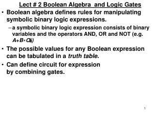
Boolean Constants and Variables • Boolean 0 and 1 do not represent actual numbers but instead represent the state, or logic level.
Three Basic Logic Operations • OR • AND • NOT
Truth Tables • A truth table is a means for describing how a logic circuit’s output depends on the logic levels present at the circuit’s inputs. A ? x B
OR Operation • Boolean expression for the OR operation: x =A + B • The above expression is read as “x equals A OR B” A x= A+B B
OR Gate • An OR gate is a gate that has two or more inputs and whose output is equal to the OR combination of the inputs. A x = A + B + C B C
Examples • Example 3-1: using an OR gate in an alarm system • Example 3-2: timing diagram
AND Operation • Boolean expression for the OR operation: x =A B • The above expression is read as “x equals A AND B” A x= AB B
AND Gate • An AND gate is a gate that has two or more inputs and whose output is equal to the AND product of the inputs. A x = ABC B C
NOT Operation • The NOT operation is an unary operation, taking only one input variable. • Boolean expression for the NOT operation:x = A • The above expression is read as “x equals the inverse of A” • Also known as inversion or complementation. • Can also be expressed as: A’ A x=A’
NOT Circuit • Also known as inverter. • Always take a single input
Describing Logic Circuits Algebraically • Any logic circuits can be built from the three basic building blocks: OR, AND, NOT • Example 1: x = A B + C • Example 2: x = (A+B)C • Example 3: x = (A+B) • Example 4: x = ABC(A+D)
Evaluating Logic-Circuit Outputs • x = ABC(A+D) • Determine the output x given A=0, B=1, C=1, D=1. • Can also determine output level from a diagram
Implementing Circuits from Boolean Expressions • y = AC+BC’+A’BC • x = AB+B’C
NOR Gate • Boolean expression for the NOR operation:x = A + B
NAND Gate • Boolean expression for the NAND operation:x = A B A AB B
Boolean Theorems (Single-Variable) • x* 0 =0 • x* 1 =x • x*x=x • x*x’=0 • x+0=x • x+1=1 • x+x=x • x+x’=1
Boolean Theorems (Multivariable) • x+y = y+x • x*y = y*x • x+(y+z) = (x+y)+z=x+y+z • x(yz)=(xy)z=xyz • x(y+z)=xy+xz • (w+x)(y+z)=wy+xy+wz+xz • x+xy=x • x+x’y=x+y
DeMorgan’s Theorems • (x+y)’=x’y’ • (xy)’=x’+y’
Alternate Logic Symbols • Step 1: Invert each input and output of the standard symbol • Change the operation symbol from AND to OR, or from OR to AND. • Examples: AND, OR, NAND, OR, INV
Logic Symbol Interpretation • When an input or output on a logic circuit symbol has no bubble on it, that line is said to be active-HIGH. • Otherwise the line is said to be active-LOW.
Which Gate Representation to Use? • If the circuit is being used to cause some action when output goes to the 1 state, then use active-HIGH representation. • If the circuit is being used to cause some action when output goes to the 0 state, then use active-LOW representation. • Bubble placement: choose gate symbols so that bubble outputs are connected to bubble inputs , and vice versa.
IEEE Standard Logic Symbols • NOT • AND • OR • NAND • NOR 1 A x A & x B A ≧1 x A & x A ≧1 x B B B