Download
1 / 10
100 likes | 205 Views
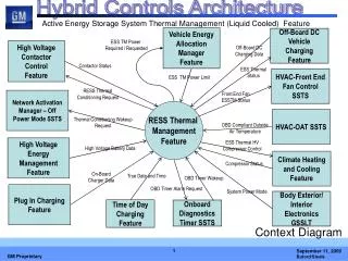
Active Energy Storage System Thermal Management (Liquid Cooled) Feature. Vehicle Energy Allocation Manager Feature. Off-Board DC Vehicle Charging Feature. ESS TM Power Required / Requested. High Voltage Contactor Control Feature. Off-Board DC Charging Data. Contactor Status.

E N D
Active Energy Storage System Thermal Management (Liquid Cooled) Feature Vehicle Energy Allocation Manager Feature Off-Board DC Vehicle Charging Feature ESS TM Power Required / Requested High Voltage Contactor Control Feature Off-Board DC Charging Data Contactor Status ESS Thermal Status HVAC-Front End Fan Control SSTS ESS TM Power Limit RESS Thermal Conditioning Request Front End Fan ESSTM Status Network Activation Manager – Off Power Mode SSTS RESS Thermal Management Feature HVAC-OAT SSTS Thermal Conditioning Wakeup Request OBD Compliant Outside Air Temperature ESS Thermal HV Compressor Control High Voltage Energy Management Feature High Voltage Battery Data Climate Heating and Cooling Feature Compressor Status On-Board Charger Data True Date and Time OBD Timer Wakeup OBD Timer Alarm Request Plug In Charging Feature System Power Mode Body Exterior/ Interior Electronics GSSLT Time of Day Charging Feature Onboard Diagnostics Timer SSTS Context Diagram
Active Energy Storage System Thermal Management (Liquid Cooled) Feature High Voltage Battery Data OBD Timer Alarm Request Predict and Configure Alarm Setting HV Heater and Control Circuit OBD Compliant Outside Air Temperature Contactor Status HV Heater Control ESS TM Power Required / Requested Determine ESS TM Power Needed and ESS TM Status Determine HV Need Off-Board DC Charging Data ESS Thermal Conditioning Request ESS TM Status HV Heater Power Allocation ESS TM Status Allocate Power for ESS Thermal Management HV Compressor Power Allocation ESS Heating Control ESS TM Power Limit On-Board Charger Data ESS Coolant Pump ESS Coolant Pump Control System Power Mode Contactor Status ESS Coolant Mode Valve Control ESS Cooling Control ESS Coolant Mode Valve Determine Wake-Up Control OBD Timer Wakeup Thermal Conditioning Wake-up Request True Date and Time Compressor Status ESS Thermal HV Compressor Control Data Flow Diagram Level 0 Front End Fan ESSTM Status
Active Energy Storage System Thermal Management (Liquid Cooled) Feature Function Allocation to Subsystem
Active Energy Storage System Thermal Management (Liquid Cooled) Feature Primitive Specifications (PSPEC)
Active Energy Storage System Thermal Management (Liquid Cooled) Feature • ESS TM Status • An enumerated (Heating/Cooling/Delta T/None) signal that communicates the status of the ESS . • High Voltage Battery Data • Data from the ESS that reports the temperature of the highest and lowest battery cell temperatures as well as the temperature of the air or fluid entering and exiting the battery pack. (ESS Cell Temperature, ESS Air Temperature, ESS Coolant Temperature) • On-Board Charger Data • Data including On-Board Charger Available Power (does not include 12V power and is de-rated for converter efficiency) • OBD Timer Alarm Request • A signal that informs the ESSTM system of when to wake-up so that the temperatures of the ESS can be evaluated. • OBD Timer Wake-Up • A signal that informs the system to wake-up the all modules so ESS TM can be evaluated. • System Power Mode • This signal is used to report the position of the ignition or vehicle system. • ESS TM Power Required /Requested • The amount of Power needed to support the conditioning of the ESS. This power is used to feed the HV ESS Heater or HV AC compressor. • OBD Compliant Outside Air Temperature • Ambient Air Temperature sensor structured to be OBD compliant • HV ESS Heater Control • Signal that controls the ESS Heater operation (via FET) • ESS Thermal HV Compressor Control • Control signal indicating the HV Electric AC Compressor need for use by ESS Thermal for input to the algorithm for summary control of the HV Electric AC Compressor. • . Program Signal Definitions
Active Energy Storage System Thermal Management (Liquid Cooled) Feature • ESS TM Power Limit • System Input which will limit the power consumed by the ESS Thermal system to provide conditioning for the battery. . • HV Heater Power Allocation • Power allocation for the battery heater control for battery conditioning. • HV Compressor Power Allocation • Power allocation for the AC compressor control for battery conditioning. • Thermal Conditioning Wake-up Request • A signal that informs the system to wake-up modules necessary for ESS Thermal Management evaluation. • ESS Thermal Conditioning Request • A signal that informs the High Voltage Contactor Control system to close the necessary contactors to provide High Voltage for ESS Thermal Management. • Contactor Status • Status of the High Voltage Contactor system. (Open, Closed, Failed) • ESS Coolant Pump Control • Controls the operation of the ESS Coolant Pump. • ESS Coolant Mode Valve Control • Controls the operation of the ESS Coolant Mode Valve. • Front End Fan ESSTM Status • Status of the ESS Thermal System Data for use in controlling the Front End Fan. Data includes High Voltage Battery Cooling System Valve Position, Battery Temperatures and targets, Battery Coolant Temperature and operational status of the ESSTM feature • Compressor Status • Actual power output of the AC Compressor and Refrigerant Temperature • Off Board Charging Data • Indicates whether or not the Off-Board DC Charging function is active. Program Signal Definitions
Active Energy Storage System Thermal Management (Liquid Cooled) Feature • Feature Activation Modes:
Active Energy Storage System Thermal Management (Liquid Cooled) Feature Pump Enable 14V VICM RESS Coolant Pump #1 (50W) Battery Pump PWM Control High Voltage Compressor 300V Pump Speed Feedback RESS Valve Drive A Gnd RESS Coolant Mode Valve RESS Valve Drive B ACCM Position Reference AC Compressor Electrical Power Position Feedback Propulsion System Active HS GMLAN Position Return ECM ECM Heater PWM Control ESS Thermal Fan Data PTEB 300V High Voltage RESS Heater Secondary Accessory Wakeup HVEM EB VITM RESS Coolant Temp RESS Inlet Coolant Temp Sensor 5V Return RESS Inlet Coolant Temp RESS Outlet Coolant Temp RESS Temp Sensor (1) … … RESS Temp Sensor (n) RESS Coolant Temp RESS Outlet Coolant Temp Sensor 5V Return Controls Architecture Reference Only: Refer to ESS Thermal (Liquid Cooled ) SSTS
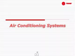
Active Energy Storage System Thermal Management (Liquid Cooled) Feature Air Conditioning Loop Battery Coolant Loop TXV#2 RESS Chiller TXV#1 BP Coolant Pump (50W) Evaporator High Voltage Battery Pack ACCM AC Compressor RESS Coolant Mode Valve EREV HVAC and Powertrain Cooling Systems
Active Energy Storage System Thermal Management (Liquid Cooled) Feature Air Conditioning Loop Battery Coolant Loop TXV#2 RESS Chiller Charger TXV#1 BP Coolant Pump (50W) Evaporator APM High Voltage Battery Pack ACCM AC Compressor RESS Coolant Mode Valve PHEV HVAC and Powertrain Cooling Systems