Download
1 / 155
1.69k likes | 2.12k Views
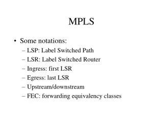
MPLS Introduction. Agenda. Introduction to MPLS LDP MPLS VPN Monitoring MPLS. MPLS Concept. At Edge: Classify packets Label them. In Core: Forward using labels (as opposed to IP addr) Label indicates service class and destination. Edge Label Switch Router (ATM Switch or Router).

E N D
Agenda • Introduction to MPLS • LDP • MPLS VPN • Monitoring MPLS
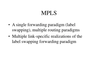
MPLS Concept • At Edge: • Classify packets • Label them • In Core: Forward using labels (as opposed to IP addr) Label indicates service class and destination Edge Label Switch Router(ATM Switch or Router) Label Switch Router (LSR) • Router • ATM switch + Tag Switch Controller Label Distribution Protocol (LDP)
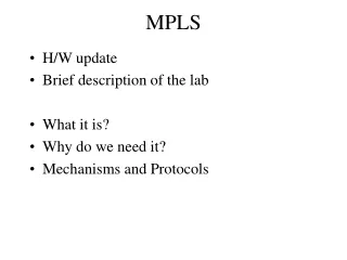
MPLS concept • MPLS: Multi Protocol Label Switching • Packet forwarding is done based on Labels. • Labels are assigned when the packet enters into the network. • Labels are on top of the packet. • MPLS nodes forward packets/cells based on the label value (not on the IP information).
MPLS concept • MPLS allows: • Packet classification only where the packet • enters the network. • The packet classification is encoded as a label. • In the core, packets are forwarded without • having to re-classify them. • - No further packet analysis • - Label swapping
1a. Existing routing protocols (e.g. OSPF, IS-IS) establish reachability to destination networks. 4. Edge LSR at egress removes(POP) label and delivers packet. 1b. Label Distribution Protocol (LDP) establishes label to destination network mappings. 2. Ingress Edge LSR receives packet, performs Layer 3 value-added services, and labels(PUSH) packets. 3. LSR switches packets using label swapping(SWAP) . MPLS Operation
Label Switch Path (LSP) IGP domain with a label distribution protocol IGP domain with a label distribution protocol LSP follows IGP shortest path LSP diverges from IGP shortest path • LSPs are derived from IGP routing information • LSPs may diverge from IGP shortest path • LSPs are unidirectional • Return traffic takes another LSP
Encapsulations ATM Cell Header GFC VPI VCI PTI CLP HEC DATA Label PPP Header (Packet over SONET/SDH) PPP Header Label Header Layer 3 Header LAN MAC Label Header MAC Header Label Header Layer 3 Header
Label Header 0 1 2 3 • Header= 4 bytes, Label = 20 bits. • Can be used over Ethernet, 802.3, or PPP links • Contains everything needed at forwarding time 0 1 2 3 4 5 6 7 8 9 0 1 2 3 4 5 6 7 8 9 0 1 2 3 4 5 6 7 8 9 0 1 Label EXP S TTL Label = 20 bits EXP = Class of Service, 3 bits S = Bottom of Stack, 1 bit TTL = Time to Live, 8 bits
Loops and TTL • In IP networks TTL is used to prevent packets to travel indefinitely in the network • MPLS may use same mechanism as IP, but not on all encapsulations • TTL is present in the label header for PPP and LAN headers (shim headers) • ATM cell header does not have TTL
Loops and TTL Label = 25 Label = 21 Label = 39 IP packetTTL = 6 IP packetTTL = 6 IP packetTTL = 6 LSR-1 LSR-3 LSR-2 IP packetTTL = 10 LSR-6 LSR-6 --> 25Hops=4 IP packetTTL = 6 IGP domain with a label distribution protocol Egress LSR-5 LSR-4 • TTL is decremented prior to enter the non-TTL capable LSP • If TTL is 0 the packet is discarded at the ingress point • TTL is examined at the LSP exit
Label Assignment and Distribution • Labels have link-local significance: • Each LSR binds his own label mappings • Each LSR assign labels to his FECs • Labels are assigned and exchanged between adjacent neighboring LSR
Label Assignment and Distribution Upstream and Downstream LSRs • Rtr-C is the downstream neighbor of Rtr-B for destination 171.68.10/24 • Rtr-B is the downstream neighbor of Rtr-A for destination 171.68.10/24 • LSRs know their downstream neighbors through the IP routing protocol • Next-hop address is the downstream neighbor 171.68.40/24 171.68.10/24 Rtr-A Rtr-B Rtr-C
Use label 40 for destination 171.68.10/24 Use label 30 for destination 171.68.10/24 In I/F In I/F In I/F In Lab In Lab In Lab Address Prefix Address Prefix Address Prefix Out I/F Out I/F Out I/F Out Lab Out Lab Out Lab 0 0 0 40 30 - 171.68.10 171.68.10 171.68.10 1 1 1 30 - 40 Next-Hop Next-Hop Next-Hop ... ... ... ... ... ... ... ... ... ... ... ... ... ... ... Unsolicited Downstream Distribution • LSRs distribute labels to the upstream neighbors 171.68.40/24 171.68.10/24 Rtr-A Rtr-B Rtr-C IGP derived routes
Use label 30 for destination 171.68.10/24 Use label 40 for destination 171.68.10/24 Request label for destination 171.68.10/24 Request label for destination 171.68.10/24 On-Demand Downstream Distribution 171.68.10/24 171.68.40/24 Rtr-A Rtr-B Rtr-C • Upstream LSRs request labels to downstream neighbors • Downstream LSRs distribute labels upon request
Label Retention Modes • Liberal retention mode • LSR retains labels from all neighbors • Improve convergence time, when next-hop is again available after IP convergence • Require more memory and label space • Conservative retention mode • LSR retains labels only from next-hops neighbors • LSR discards all labels for FECs without next-hop • Free memory and label space
Label Distribution Modes • Independent LSP control • LSR binds a Label to a FEC independently, whether or not the LSR has received a Label the next-hop for the FEC • The LSR then advertises the Label to its neighbor • Ordered LSP control • LSR only binds and advertise a label for a particular FEC if: • it is the egress LSR for that FEC or • it has already received a label binding from its next-hop
Router Example: Forwarding Packets Address Prefix Address Prefix Address Prefix I/F I/F I/F 128.89 128.89 128.89 1 0 0 171.69 1 171.69 1 … … … … 128.89 0 0 1 128.89.25.4 Data 0 128.89.25.4 Data 1 128.89.25.4 Data 128.89.25.4 Data Packets Forwarded Based on IP Address 171.69
MPLS Example: Routing Information Out I’face OutLabel Out I’face OutLabel Out I’face OutLabel In Label Address Prefix In Label Address Prefix In Label Address Prefix 128.89 1 128.89 0 128.89 0 171.69 1 171.69 1 … … … … … … 128.89 0 0 1 You Can Reach 128.89 Thru Me You Can Reach 128.89 and 171.69 Thru Me 1 Routing Updates (OSPF, EIGRP, …) 171.69 You Can Reach 171.69 Thru Me
MPLS Example: Assigning Labels Out I’face Out I’face Out I’face In Label Address Prefix In Label Address Prefix In Label Address Prefix OutLabel OutLabel OutLabel - 128.89 1 4 4 128.89 0 9 9 128.89 0 - - 171.69 1 5 5 171.69 1 7 … … … … … … … … … … … … 128.89 0 0 1 Use Label 9 for 128.89 Use Label 4 for 128.89 and Use Label 5 for 171.69 1 Label Distribution Protocol (LDP) (downstream allocation) 171.69 Use Label 7 for 171.69
MPLS Example: Forwarding Packets Out I’face Out I’face Out I’face In Label Address Prefix In Label Address Prefix In Label Address Prefix OutLabel OutLabel OutLabel - 128.89 1 4 4 128.89 0 9 9 128.89 0 - - 171.69 1 5 5 171.69 1 7 … … … … … … … … … … … … 128.89 0 0 1 128.89.25.4 Data 9 128.89.25.4 Data 1 128.89.25.4 Data 4 128.89.25.4 Data Label Switch Forwards Based on Label
Agenda • Introduction to MPLS • LDP • MPLS VPN • Monitoring MPLS
MPLS Unicast IP Routing • MPLS introduces a new field that is used for forwarding decisions. • Although labels are locally significant, they have to be advertised to directly reachable peers. • One option would be to include this parameter into existing IP routing protocols. • The other option is to create a new protocol to exchange labels. • The second option has been used because there are too many existing IP routing protocols that would have to be modified to carry labels.
Label Distribution Protocol • Defined in RFC 3036 and 3037 • Used to distribute labels in a MPLS network • Forwarding equivalence class • How packets are mapped to LSPs (Label Switched Paths) • Advertise labels per FEC • Reach destination a.b.c.d with label x • Neighbor discovery • Basic and extended discovery
MPLS Unicast IP Routing Architecture LSR Control plane Exchange of routing information Routing protocol IP routing table Exchange of labels Label distribution protocol Data plane Incoming IP packets Outgoing IP packets IP forwarding table Incoming labeled packets Outgoing labeled packets Label forwarding table
10.1.1.1 10.0.0.0/8 1.2.3.4 10.1.1.1 L=5 10.1.1.1 MPLS Unicast IP Routing: Example LSR Control plane OSPF: 10.0.0.0/8 OSPF: 10.0.0.0/8 1.2.3.4 10.0.0.0/8 1.2.3.4 RT: LIB: Data plane FIB: LFIB:
10.1.1.1 10.0.0.0/8 1.2.3.4 , L=3 L=3 10.1.1.1 L=3 10.1.1.1 L=5 10.1.1.1 L=5 L=3 MPLS Unicast IP Routing: Example LSR Control plane OSPF: 10.0.0.0/8 OSPF: 10.0.0.0/8 1.2.3.4 RT: 10.0.0.0/8 1.2.3.4 LDP: 10.0.0.0/8, L=5 LIB: 10.0.0.0/8 Next-hop L=3, Local L=5 LDP: 10.0.0.0/8, L=3 Data plane FIB: LFIB:
Label Allocation in Packet-Mode MPLS Environment Label allocation and distribution in packet-mode MPLS environment follows these steps: • 1. IP routing protocols build the IP routing table. • 2. Each LSR assigns a label to every destination in the IP routing table independently. • 3. LSRs announce their assigned labels to all other LSRs. • 4. Every LSR builds its LIB, LFIB data structures based on received labels.
Building the IP Routing Table • IP routing protocols are used to build IP routing tables on all LSRs. • Forwarding tables (FIB) are built based on IP routing tables with no labeling information.
Allocating Labels Router B assigns label 25 to destination X. • Every LSR allocates a label for every destination in the IP routing table. • Labels have local significance. • Label allocations are asynchronous.
Outgoing action is POP as B has received no label for X from C. Local label is stored in LIB. LIB and LFIB Set-up Router B assigns label 25 to destination X. LIB and LFIB structures have to be initialized on the LSR allocating the label.
X = 25 X = 25 X = 25 Label Distribution The allocated label is advertised to all neighbor LSRs, regardless of whether the neighbors are upstream or downstream LSRs for the destination.
Receiving Label Advertisement X = 25 X = 25 X = 25 • Every LSR stores the received label in its LIB. • Edge LSRs that receive the label from their next-hop also store the label information in the FIB.
Label lookup is performed in LFIB, label is removed. A B C E IP lookup is performed in FIB, packet is labeled. Interim Packet Propagation IP: X Lab: 25 IP: X Forwarded IP packets are labeled only on the path segments where the labels have already been assigned.
X = 47 X = 47 Further Label Allocation Router C assigns label 47 to destination X. Every LSR will eventually assign a label for every destination.
X = 47 X = 47 Receiving Label Advertisement • Every LSR stores received information in its LIB. • LSRs that receive their label from their next-hop LSR will also populate the IP forwarding table (FIB).
X = 47 X = 47 Populating LFIB • Router B has already assigned label to X and created an entry in LFIB. • Outgoing label is inserted in LFIB after the label is received from the next-hop LSR. LFIB on B Label Action Next hop 25 47 C
Label lookup is performed in LFIB, label is switched. Ingress LSR Egress LSR A B C E IP lookup is performed in FIB, packet is labeled. Label lookup is performed in LFIB, label is removed. Packet Propagation Across MPLS Network IP: X Lab: 25 Lab: 47 IP: X
Convergence in Packet-mode MPLS Steady State Description • After the LSRs have exchanged the labels, LIB, LFIB and FIB data structures are completely populated.
Link Failure Actions • Routing protocol neighbors and LDP neighbors are lost after a link failure. • Entries are removed from various data structures.
Routing Protocol Convergence Routing protocols rebuild the IP routing table and the IP forwarding table.
MPLS Convergence LFIB and labeling information in FIB are rebuilt immediately after the routing protocol convergence, based on labels stored in LIB.
MPLS Convergence After a Link Failure • MPLS convergence in packet-mode MPLS does not impact the overall convergence time. • MPLS convergence occurs immediately after the routing protocol convergence, based on labels already stored in LIB.
Link Recovery Actions • Routing protocol neighbors are discovered after link recovery.
C — pop C IP Routing Convergence After Link Recovery C • IP routing protocols rebuild the IP routing table. • FIB and LFIB are also rebuilt, but the label information might be lacking.
MPLS Convergence After a Link Recovery • Routing protocol convergence optimizes the forwarding path after a link recovery. • LIB might not contain the label from the new next-hop by the time the IP convergence is complete. • End-to-end MPLS connectivity might be intermittently broken after link recovery. • Use MPLS Traffic Engineering for make-before-break recovery.
LDP Session Establishment • LDP and TDP use a similar process to establish a session: • Hello messages are periodically sent on all interfaces enabled for MPLS. • If there is another router on that interface it will respond by trying to establish a session with the source of the hello messages. • UDP is used for hello messages. It is targeted at “all routers on this subnet”multicast address (224.0.0.2). • TCP is used to establish the session. • Both TCP and UDP use well-known LDP port number 646 (711 for TDP).
LDP Neighbor Discovery UDP: Hello (1.0.0.2:1064 224.0.0.2:646) UDP: Hello (1.0.0.2:1065 224.0.0.2:646) UDP: Hello (1.0.0.2:1066 224.0.0.2:646) • LDP Session is established from the router with higher IP address. MPLS_B 1.0.0.2 TCP (1.0.0.2:1043 1.0.0.1:646) UDP: Hello (1.0.0.1:1050 224.0.0.2:646) TCP (1.0.0.4:1066 1.0.0.2:646) UDP: Hello (1.0.0.1:1051 224.0.0.2:646) NO_MPLS_C UDP: Hello (1.0.0.1:1052 224.0.0.2:646) MPLS_A 1.0.0.3 1.0.0.1 TCP (1.0.0.4:1065 1.0.0.1:646) UDP: Hello (1.0.0.4:1033 224.0.0.2:646) UDP: Hello (1.0.0.4:1034 224.0.0.2:646) UDP: Hello (1.0.0.4:1035 224.0.0.2:646) MPLS_D 1.0.0.4
LDP Session Negotiation MPLS_A • Peers first exchange initialization messages. • The session is ready to exchange label mappings after receiving the first keepalive. MPLS_B Establish TCP session 1.0.0.1 1.0.0.2 Initialization message Initialization message Keepalive Keepalive
18 17 19 10.1.1.1 10.1.1.1 10.1.1.1 FIB 10/8 NH, 17 FIB 10/8 NH, 18 FIB 10/8 NH FIB 10/8 NH, 19 10.1.1.1 LFIB 35 17 LFIB 17 18 LFIB 19 untagged LFIB 18 19 Double Lookup Scenario MPLS Domain • Double lookup is not an optimal way of forwarding labeled packets. • A label can be removed one hop earlier. 10.0.0.0/8 L=17 10.0.0.0/8 L=18 10.0.0.0/8 L=19 10.0.0.0/8 Double lookup is needed: 1. LFIB: remove the label. 2. FIB: forward the IP packet based on IP next-hop address.