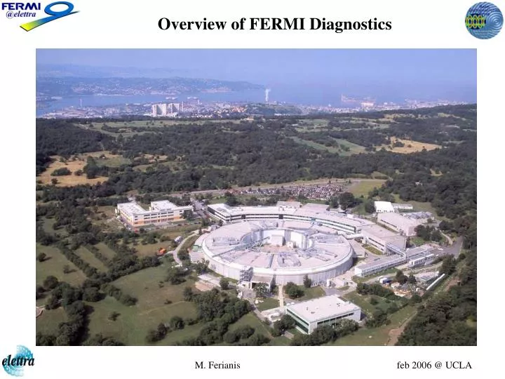
Overview of FERMI Diagnostics
210 likes | 457 Views
Overview of FERMI Diagnostics. FERMI @ ELETTRA. FERMI footprint. FERMI main parameters. FERMI layout (...work in progress). Laser heater. spreader Energy/ b H, V collimators dump. X-band linearizer. Guidelines of diagnostics for FERMI. accurate photo-injector characterisation:

Overview of FERMI Diagnostics
E N D
Presentation Transcript
Overview of FERMI Diagnostics M. Ferianis feb 2006 @ UCLA
FERMI @ ELETTRA M. Ferianis feb 2006 @ UCLA
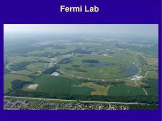
FERMI footprint M. Ferianis feb 2006 @ UCLA
FERMI main parameters M. Ferianis feb 2006 @ UCLA
FERMI layout (...work in progress) Laser heater spreader Energy/ bH, V collimators dump X-band linearizer M. Ferianis feb 2006 @ UCLA
Guidelines of diagnostics for FERMI • accurate photo-injector characterisation: emittance, charge profile, energy spread • seeded FEL scheme: whole bunch / fresh bunch (bunch core) calls for slice measurements: longitudinal charge profile, emittance, energy spread • transverse and longitudinal overlap between e- beam and laser high resolution BPM and bunch arrival monitors shot-to-shot feedbacks • stability of output FEL radiation • mm to sub-mm bunch length; currently two options: medium bunch: LB= 0.21mm (700fs) short FEL pulse long bunch: LB= 0.57mm (1.9ps) long FEL pulse M. Ferianis feb 2006 @ UCLA
Some relevant beam parameters for diagnostics *calculated assuming a normalized emittance of 1.2 mm mrad M. Ferianis feb 2006 @ UCLA
Guidelines of diagnostics for FERMI • Injector diagnostic beamline • BC1 diags • 1st RF deflector @ 220MeV (down-stream BC1) • BC2 diags • 2nd RF deflector @ 1.2 GeV • pre-FEL diagnostic station (downstream the spreader) • post-modulator diagnostic station • intra-radiator diagnostics (multipurpose pop-ins) • post radiator diagnostic station (FEL diags) M. Ferianis feb 2006 @ UCLA
Currently addressed issues on Diagnostics • review of FERMI parameters for diags. • the team @ ELETTRA: dynamically growing... • overview of main FERMI diagnostics and associated measurements • integration of diagnostics into the machine, i.e. defining: • dedicated machine optics • vacuum chamber x-sections • alignment strategy • RF power needs for diags • optical clock (laser pulse) • Conceptual Design Report write-up M. Ferianis feb 2006 @ UCLA
LINAC1 LINAC2 LINAC3 LINAC4 FEL1 FEL2 BC1 BC2 Laser Heater X SPRD Gun S0A/B Gun / injector Diagnostics • Gun: • Energy/energy spread • Charge • Spot size • Position • Bunch length • Thermal emittance M. Ferianis feb 2006 @ UCLA
775 nm seed laser derived from 1550 nm timing signal 120 kW, 10 ps LINAC4 FEL2 FEL1 LINAC1 LINAC2 LINAC3 Laser Heater : Electron beam timing relative to optical pulse Electron beam current profile Slice emittance Cross-polarized 5-period undulators YAG screen, BPM YAG screen, BPM BC2 BC1 Laser Heater X Matching quads into linac SPRD Matching quads into heater Gun S0A/B Laser heater based diagnostics W.Graves, MIT S.Spampinati, ELETTRA M. Ferianis feb 2006 @ UCLA
LINAC1 LINAC2 LINAC3 LINAC4 FEL1 FEL2 BC1 BC2 Laser Heater X SPRD Gun S0A/B BC1 & BC2 Diagnostics • Energy, Energy jitter, Vertical slice emittance: BMP –collimator -screen • Bunch length monitor: CSR output power detection to feedback loop • Micro-bunching: CSR output for detection by THz spectrometer. • Bunch arrival time measurements: fs Streak camera (ref pulse) • wide band ring electrode with EO acquisition • Bunch length, compressor tuning: • BC1: 1stRF Deflector,streak camera for OSR • BC2: 2nd RF deflector, EO sampling M. Ferianis feb 2006 @ UCLA
DIAGS FEL1 LINAC4 LINAC3 LINAC2 FEL2 LINAC1 BC1 BC2 Laser Heater X SPRD Gun S0A/B Overview of FERMI @ Elattra Diagnostics Diagnostics station at the end of linac : Vertical and Horizonthal RF deflecting cavity: Slice emittance CSR effect on horizonthal emittance Slice Energy Spread EOS bunch arrival time monitor: Bunch arrival time Arrival time jitter Bunch length Features: single shot (SLAC spatial convertion scheme, 100fsec resolution, MLO or SEED laser pulses as a probe) M. Ferianis feb 2006 @ UCLA
DIAGS FEL1 LINAC4 LINAC3 LINAC2 FEL2 LINAC1 BC1 BC2 Laser Heater X SPRD Gun S0A/B Overview of FERMI @ Elattra Diagnostics FEL 1&2 : Entrance of modulators: X,Y position and divergence: high precision cavity BPM Intra - radiators: e-beam and FEL radiation position and spot size: pop-in station with YAG screens e-beam X,Y position: cavity or button BPM microbunching and power growth: OTR/CTR monitorinig during operation CDR Exit of last radiator FEL radiation: (under development by user group): Single shot Spectral distribution monitor FEL radiation arrival time by respect to user laser determined by cross correlation techniques (De Silvestri) and advanced streak cameras. M. Ferianis feb 2006 @ UCLA
Traveling wave deflector performances for low energy case EB= 240 MeV; n=1.5 mm mrad; a=20 mm vg/c=0.0312 (L=1m=100ns) a=12.5 mm; vg/c=0.0123(L=1m=270ns) fRF=2.998 GHz; D=45 m; S=45 m; =90 deg; Long bunch: 1.5 mm Short bunch: 0.4 mm Ldef=2m M. Ferianis feb 2006 @ UCLA
Standing wave deflector: performances for high energy case EB= 1.2 GeV; n=1.5 mm mrad; a=20 mm, =1 F=0.85s a=12.5 mm, =1 F=1.0s fRF=2.998 GHz; D=45 m; S=45 m; =90 deg; M. Ferianis feb 2006 @ UCLA
Beam pipe radius: to be defined according to Vacuum & Zbeam current value R=6mm; ID gap (vacuum side) calls for R=3.5mm Extraction waveguide radial position: to be checked with simulation Optimum position for the RF connecotr on the waveguide Signal amplitude dependance on Qbunch (analytical eval.) Achievable mechanical accuracy on prototype: 10mm Setting up the RF test bench (Network An.@20GHz): BPM rigidly fixed to supportcoaxial moving wire, over ±1mm, acuracy and reproducibility <2mm prototype issues: no UHV, flanged + RF sliding contacts, equipped with SMA connectors (DC to 18 GHz) Cavity BPM in collaboration with M Poggi, INFN PD M. Ferianis feb 2006 @ UCLA
~550 mV/ps Phase monitor (collaboration with Desy) Principle: • Isolated impedance-matched Ring Electrode installed in a „thick Flange“ • Broadband, Position independent Signal • One installed after the Gun, each magnetic Chicane (both BCs, the Collimator + before Undulator) • BC´s: Energy Fluctuations -> Phase Fluctuations TOF Measurement: Resolution ≈ 0.2° or 0.4 ps • Fast timing signals with sub ps resolution • Very simple design of pickup • Two output signal provided (left & right) Phase Monitor Courtesy: H. Schlarb, F.Löhl M. Ferianis feb 2006 @ UCLA
1.3 GHz Master Laser Oscillator DAC ~ piezo- fiber- stretcher ~ ~ ~ ~ ~ ~ ~550 mV/ps EO acquisition of the wide band ring electorde signal Courtesy: H. Schlarb, F.Löhl MLO RF master piezo- controller VM 1.3 GHz 10 GHz DOOCS DOOCS 200 MHz 81 MHz limiter clock trigger ADC 100 MHz 12 / 14 Bit Mach-Zehnder interferometer 200 MHz 10 kHz EOM phase monitor 12 dB bias- voltage BPhM Later: limiter M. Ferianis feb 2006 @ UCLA
Impact from vacuum chamber sections M. Ferianis feb 2006 @ UCLA
Timing and Synchronization M. Ferianis feb 2006 @ UCLA