Download
1 / 75
760 likes | 1.01k Views
Basic Digital Logic. Digital Electronics Number Systems and Logic Electronic Gates Combinational Logic Sequential Circuits ADC – DAC circuits Memory and Microprocessors Hardware Description Languages. Weekly Structure. Lectures Monday, Tuesday, Wednesday

E N D
Digital Electronics • Number Systems and Logic • Electronic Gates • Combinational Logic • Sequential Circuits • ADC – DAC circuits • Memory and Microprocessors • Hardware Description Languages
Weekly Structure • Lectures Monday, Tuesday, Wednesday • Slides in ppt and pdf format on support website: • http://www.roletech.net/comp360.htm (follow link from course website) • Tutorials anytime - Sample Questions on website.
The lecture today • Digital vs Analog data • Binary inputs and outputs • Binary, octal, decimal and hexadecimal number systems • Other uses of binary coding.
Analog/Analogue Systems • Analogue Systems • V(t) can have any value between its minimum and maximum value V(t)
Digital Systems • Digital Systems • V(t) must take a value selected from a set of values called an alphabet • Binary digital systems form the basis of almost all hardware systems currently V(t) 1 0 1 0 1 For example, Binary Alphabet: 0, 1.
Slide example • Consider a child’s slide in a playground: a set of discrete steps continuous movement levels
5 Volt Input Range for 1 Output Range for 1 2.8 2.4 0.8 Input Range for 0 Output Range for 0 0.4 0 Volt Relationship between Analogue and Digital systems • Advantages of Digital Systems • Analogue systems: slight error in input yields large error in output • Digital systems more accurate and reliable • Computers use digital circuits internally • Interface circuits (for instance, sensors and actuators) are often analogue
Exercise • Explain whether the following are analog or digital: • A photograph or painting • A scanned image • Sound from a computer’s loud speaker • Sound file stored on disc
Binary Inputs and Outputs • Coding: • A single binary input can only have two values: True or False (Yes or No) (1 or 0)
Binary • More bits = more combinations 0 0 0 1 1 0 1 1 • Each additional input doubles the number of combinations we can representi.e. with n inputs it is possible to represent 2n combinations
Combinations • Example 1: • How many combinations are possible with 10 binary inputs? • Example 2: • What is the minimum number of bits needed to represent the digits ‘0’ to ‘9’ as a binary code?”
Decimal systems • Number Representation • Difficult to represent Decimal numbers directly in a digital system • Easier to convert them to binary • There is a weighting system: eg 403 = 4 x 100 + 0 x 10 + 3 x 1 or in, powers of 10: 40310= 4x10² + 0x101 + 3x100 = 400 + 0 + 3
Binary Inputs and Outputs • Both Decimal and Binary numbers use a positional weighting system, eg: 10102 = 1x23+0x22+1x21+0x20 = 1x8 + 0x4 + 1x2 + 0x1 = 1010
Binary to decimal • Multiply each 1 bit by the appropriate power of 2 and add them together. 100000112 = ……………….10 ? 1010011002 = ……………………10 ?
Binary Inputs and Outputs • Number Representation - Binary to decimal • A decimal number can be converted to binary by repeated division by 2 15510 = 100110112
Decimal to Binary An alternative way is to use the “placement” method 128 goes into 155 once leaving 27 to be placed So 64 and 32 are too big (make them zero) 16 goes in once leaving 11 and so on…
Representations • There are different ways of representing decimal numbers in a binary coding • BCD or Binary Coded Decimal is one example. • Each decimal digit is replaced by 4 binary digits
Binary Inputs and Outputs • 6 of the possible 16 values unused • example 45310 = 0100 0101 0011BCD • Note that BCD code is longer than a direct representation in natural binary code: • 453 = 111000101
Binary Inputs and Outputs • Hexadecimal and Octal • Writing binary numbers as strings of 1s and 0s can be very tedious • Octal (base 8) and Hexadecimal (base 16) notations can be used to reduce a long string of binary digits. Notice that hexadecimal requires 15 symbols (each number system needs 0 – base-1 symbols) and therefore A – F are used after 9.
Octal as shorthand for Binary • Each octal digit corresponds to 3 binary bits To convert a binary string: 10011101010011 Split into groups of 3: 010 011 101 010 011 2 3 5 2 3 Thus 100111010100112 = 235238
Similarly with Hexadecimal • Each hex digit corresponds to 4 binary bits To convert a binary string: 10011101010011 Split into groups of 4: 0010 0111 0101 0011 Thus 100111010100112 = ……………16 ?
Binary inputs and outputs • Colour codes • You often see hex used in graphic design programs for the red, blue and green components of a colour: • FF0000 represents red, for example. • How many bits are used to represent each colour? • How many different colours can be represented?
Binary Inputs and Outputs • Characters • Three main coding schemes used: ASCII (widespread use), EBCDIC (not used often) and UNICODE (new) • ASCII table (in hex) :
Gray Codes • Other codes exist for specific purposes • Gray codes provide a sequence where only one bit changes for each increment • Allows increments without ambiguity due to bits changing at different times. • E.g. changing from 3 to 4, normal binary has all three bits changing 011 -> 100. Depending on the order in which the bits change any intermediate value may be created.
Summary • Support website • Analogue and Digital • Binary Number Systems • Coding schemes considered were: • Natural Binary • BCD • Octal representation • Hexadecimal representation • ASCII
Exercises • You should practice conversions between binary, octal, decimal and hexadecimal. • You should be able to code decimal to BCD (and BCD to decimal). • You should be able to explain and give examples of digital and analogue data.
Binary, Hex, & BCD:Binary Number System • Most digital systems deal with groups of bits in even powers of 2, such as 8, 16, 32, and 64 bits • 8-bit Binary number - weighted values of each bit
Binary, Hex, & BCD:Binary Number System • Example: Convert 1011 1010 to its decimal equivalent 128 + 0 + 32 + 16 + 8 + 0 + 2 + 0 = 18610
Binary, Hex, & BCD:Binary Number System • Fractional Binary Numbers • Example: Convert 1011.1010 to its decimal equivalent 8 + 0 + 2 + 1 + 0.5 + 0 + 0.125 + 0 = 11.62510
Remainder Remainder Remainder Remainder Remainder Remainder 2 2 Quotient Quotient Quotient Quotient 2 2 2 2 Review – Decimal to Binary 100110 Example 3810 = _______2 LSB 38 0 1 19 9 1 4 0 2 0 1 1 MSB
Review – Decimal to Binary 100110 Example 3810 = _______2 0 + 0 + 32 + 0 + 0 + 4 + 2 + 0 = 3810
Binary, Hex, & BCD:Hexadecimal Number System • Most digital systems deal with groups of bits in even powers of 2, such as 8, 16, 32, and 64 bits • Hexadecimal uses groups of 4 bits • Base 16 • 16 possible symbols • 0 thru 9 and A thru F • Easier handling of long binary strings
Binary, Hex, & BCD:Converting Hex to Decimal • Multiply each digit by its positional weight Example: 24316 = 2 x (162) + 4 x (161) + 3 x (160) = 512 + 64 + 3 = 57910
Binary, Hex, & BCD:Converting Decimal to Hex • Use repeated division method • Divide decimal number by 16 • First remainder is LSB; last is MSB • Note: when done on calculator, the fractional portion can be multiplied by 16 to get the remainder
Remainder Remainder Remainder 16 16 Quotient Quotient Quotient 16 Example 57910 = _____16 243 579 3 LSD 36 4 2 2 MSD 0
Binary, Hex, & BCD:Converting Hex to Binary • Example: 9F216 = 9 F 2 = 1001 1111 0010 = 1001111100102
Binary, Hex, & BCD:Converting Binary to Hex • Group bits in fours starting with LSB • Convert each group to hex digit • Add leading zeros to left of MSB of last group, as needed
Binary, Hex, & BCD:Converting Binary to Hex • Example: 11101001102 =0011 1010 0110 = 3 A 6 = 3A616 • Counting in hex reset & carry after F
TTL Logic Chips-Basic Circuitry • Power & Ground (on basic gates - 14 pin DIP) • Pin 14 – Vcc (+5V) • Pin 7 – GND • Absolute limits 7400 NAND Gate Data Sheet
TTL 74 Series Logic Chips • Logic Level voltage ranges • VIN High = 2.0Vmin • VIN Low = 0.8Vmax • VOUT High = 2.4Vmin • VOUT Low = 0.4V max • Indeterminate voltages Any voltage between 0.8V and 2.0V on an input can not be guaranteed to be either high or low • Current capabilities • IIN High = 40uA • IIN Low = -1.6mA • IOUT High = -0.4mA • IOUT Low = 16mA
TTL 74 Series Logic Chips • Fan out Fan out (HIGH) = IOH(max) / IIH(max) For 7400: 400uA/40uA = 10 Fan out (LOW) = IOL(max) / IIL(max) For 7400: 16mA/1.6mA = 10 Propagations delays • How long does it take the output to change after a change has happened at the inputs
Data Sheets • Floating inputs • What happens if you don’t connect an input to a high or low • CMOS family • MOSFET switches instead of bipolar junction transistor switches • Faster than most standard TTL chips • More susceptible to static electricity
Review of Logic Functions NAND GateTruth Table NAND: AB A × B A & B
Review of Logic Functions XNOR GateTruth Table XNOR: A + B A $ B
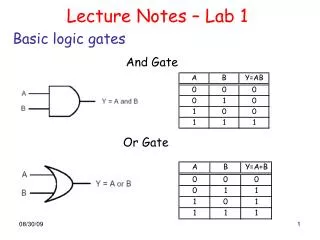
Review of Logic Functions OR GateTruth Table OR: A + B A # B
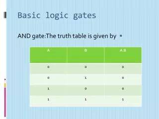
Review of Logic Functions AND GateTruth Table AND: AB A × B A & B
Review of Logic Functions NOR GateTruth Table OR: A + B A # B
Review of Logic Functions XOR GateTruth Table XOR: A + B A $ B