ATLAS
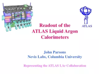
ATLAS. Readout of the ATLAS Liquid Argon Calorimeters John Parsons Nevis Labs, Columbia University Representing the ATLAS LAr Collaboration. LHC : pp collisions @ √ s = 14 TeV Design Luminosity : 10 3 4 cm -2 s -1. Liquid Argon Calorimeters Barrel EM ~ 110208 channels End Cap EM ~ 63744


ATLAS
E N D
Presentation Transcript
ATLAS Readout of theATLAS Liquid ArgonCalorimetersJohn ParsonsNevis Labs, Columbia UniversityRepresenting the ATLAS LAr Collaboration
LHC :pp collisions @ √s = 14 TeV Design Luminosity :1034 cm-2 s-1 Liquid Argon Calorimeters Barrel EM ~110208 channels End Cap EM ~63744 HEC~5888 FCAL ~3584 In total ~190 K channels J. Parsons, Siena, October 2002
Requirements of ATLAS LAr Frontend Crate Electronics • read out 190k channels of calorimeter • dynamic range 16 bits • measure signals at bunch crossing frequency of 40 MHz (ie. every 25 ns) • store signals during L1 trigger latency of up to 2.5 s (100 bunch crossings) • digitize and read out 5 samples/channel at a max. L1 rate of 100 kHz • measure deposited energies with resolution < 0.25% • measure times of energy depositions with resolution << 25 ns • high density (128 channels per board) • low power ( 0.8 W/channel) • high reliability over expected lifetime of > 10 years • must tolerate expected radiation levels (10 yrs LHC, no safety factors) of: • TID 5 kRad • NIEL 1.6E12 n/cm2 (1 MeV eq.) • SEU 7.7E11 h/cm2 (> 20 MeV) J. Parsons, Siena, October 2002
Overview of ATLAS Liquid Argon (LAr) Calorimeter Readout J. Parsons, Siena, October 2002
ATLAS LAr Frontend Crate Electronics Overview • On-detector electronics • Boards tested functionally on Mod 0 • ATLAS rad-tol boards being finalized Controller : 116 boards Calibration : 116 boards @ 128 ch Front End Board (FEB) : 1524 boards @ 128 ch Tower builder(TBB) : 120 boards @ 32 ch J. Parsons, Siena, October 2002
Module 0 Electronics Experience • Approx. 6000 channels of full functionality “Module 0” boards were developed and produced • 50 FEB , 12 calib, 2 TBB • Provided verification of electronics design concepts • Have been operating reliably in testbeam runs with Module 0 and production calorimeter runs at CERN for past several years • Performance meets or exceed ATLAS specifications (for sample results, see other ATLAS LAr talks at this conference) • Due to schedule, Mod 0 electronics were developed without requiring radiation tolerance • the main task remaining in the development of the final ATLAS boards was to radiation harden the designs, and in particular to replace several FPGAs and other COTs with custom rad-tol ICs J. Parsons, Siena, October 2002
Radiation Tolerance Requirements Barrel FEC Endcap FEC • Over 10 yrs at design luminosity, on-detector electronics must tolerate significant exposure to ionizing rad’n, neutrons, and other hadrons • TID 5 kRad • NIEL 1.6E12 n/cm2 (1 MeV eq.) • SEU 7.7E11 h/cm2 (> 20 MeV) • Rad’n qualification requires extensive testing of components, including large SAFETY FACTORS due to uncertainties in simulation, possible low dose rate effects, and possible lot-to-lot variations • Combined safety factors can be as high as 70 (!!) • In addition to total damage, need to pay careful attention to possible single event upsets (SEU) of digital logic J. Parsons, Siena, October 2002
Radiation Hardening the ATLAS LAr Readout • Reduce/avoid use of COTs • Developed 12 different custom ASICs using specialized rad-tol processes: • 9 DMILL chips • 3 DSM chips (using rad-tol standard cell library) • Paid careful attention in ASIC design to “harden” design against SEU. • Triple-redundancy and majority voting techniques for critical registers • Parameter storage with Hamming code and EDC logic eg. DSM SCA Controller reduces req’d FEB Reset rate by factor ~ 70 (residual rate < 1 FEB/hr in whole system) • Radiation qualification process requires TESTING, TESTING, TESTING!! J. Parsons, Siena, October 2002
Controller Board Overview • Provide redundant optical links to off-detector control electronics for TTC (trigger/timing) and SPAC (serial control for downloading/reading back configuration parameters) • Provide (bussed) SPAC and (point-to-point) TTC signals to rest of boards in ½ crate • Prototype being developed now; to be delivered end Oct. for beginning of set up of system crate test J. Parsons, Siena, October 2002
Calibration Board Overview • Generate 0.1% precision calibration pulses • Rise time < 1 ns • Current pulse amplitude from 200 nA up to 10 mA • Delay programmable from 0 to 24 ns in 1 ns steps • Number of current pulsers per CALIB board is 128 J. Parsons, Siena, October 2002
10 uH 5 Ώ 0.1% 50 Ώ 0.1% Overview of Main CALIB Components DMILL AMS COTS Enable Spac VDAC 6 CALogic 128 opamp 10 μV offset 1 DAC 16 bits 1 SPAC 128 Output signals IDAC TTC CMD 16 driver 128 HF switch 2 delay 1 TTCRx 4 pos. Vreg and 1 (non-essential?) neg. Vreg J. Parsons, Siena, October 2002
SPAC2 CALlogic TTCRx Delay DAC Opamps & switch 8 outputs 8 Channel CALIB Prototype • Include digital control plus analog chain for 8 channels • 3 boards received in April 02 • Design of full-sized 128 channel board is underway; delivery by Nov. J. Parsons, Siena, October 2002
Frontend Board Overview • functionality includes: • receive input signals from calorimeter • amplify and shape them • store signals in analog form using SCA while awaiting L1 trigger • digitize signals for triggered events • transmit output data bit-serially over optical link off detector • provide analog sums to L1 trigger sum tree J. Parsons, Siena, October 2002
SCA Analog Memory • Provides analog signal storage during L1 latency of up to 2.5 s (100 bunch crossings) • 144 cell pipeline, to give multi-event derandomizing buffer • Design developed in rad-soft technology, and then successfully migrated to rad-hard DMILL version • Some performance numbers: • Signal range 3.8V • Noise 300 V • Fixed Pattern Noise 190 V • DC Dynamic range 13.3 bits • Cell-to-Cell DC gain spread < 0.02% • Chan-to-chan offset spread 10mV RMS • Voltage droop < 3mV/ms • To automatically test > 50000 SCA chips, a robotic test station was developed • SCA tests underway (yield ~ 70%); finish by end 2002 • Same setup already used to test > 50000 Shaper chips J. Parsons, Siena, October 2002
DMILL AMS Overview of main FEB components DSM COTS • 10 different custom rad-tol ASICs, relatively few COTs 128 input signals 32 0T 32 Shaper 32 SCA 16 ADC 8 GainSel 1 MUX 1 fiber to ROD Analog sums to TBB 2 LSB 2 SCAC 1 Config. 1 GLink TTC, SPAC signals 14 pos. Vregs +6 neg. Vregs 2 DCU 7 CLKFO 1 TTCRx 1 SPAC J. Parsons, Siena, October 2002
FEB Prototype 128 I/P signals • 128 channels/FEB • components on both sides to achieve density • Need neg. Vregs before launching 20 FEB pre-production for system crate test, last major milestone before beginning production Preamps Shapers SCAs ADCs GainSel SCA Controllers SPAC TTCRx O/P optical link J. Parsons, Siena, October 2002
FEB Optical Links • one GLink output link per FEB, with rate of 1.6 Gbps Total raw data rate from 1524 LAr FEBs 2.4 Tera bps 1.6 Gb/s J. Parsons, Siena, October 2002
Overview of ATLAS Liquid Argon (LAr) Calorimeter Readout J. Parsons, Siena, October 2002
Readout Driver (ROD) Overview • Process raw data in real time @ 100 kHz L1 rate: • Apply calibration constants • From 5 time samples per channel, calculate (via optimal filtering): • Deposited energy • Time of energy deposition • Pulseshape quality (2) • Format processed data and transmit to L2/DAQ • Perform histogramming + monitoring of raw data • ROD Demo program allowed successful prototyping of several different commercial DSPs • selected 600 MHz TI 6414 • ROD prototype being finalized • DSP on plug-in daughter board allows “staging” of ROD system for initial running (at lower L1 rate) by originally producing only 50% of the processing power J. Parsons, Siena, October 2002
Some 6414 ROD Demonstrator Results • 600 MHz TI 6414 can process 128 channels (one FEB) in less than 10 s • Independent DMAs for I/P and O/P streams provide enough I/O bandwidth without significant impact on processing • DSP memory sufficient to store “reasonable” set of histo’s • Due to 6414 cache structure, simulator gives overly optimistic results • Design of final Double Processing Unit (PU) with two 6414 DSPs, and of ROD Motherboard incorporating 4 Double PUs, is underway • Prototypes should be available in early 2003 J. Parsons, Siena, October 2002
Summary • Radiation hardening the Module 0 electronics designs has required a VERY significant effort over several years • development of a large number of custom ASICs • extensive irradiation test programs for both custom ASICs and COTs • All components are in, or will move into, production by the end of 2002 • Final prototypes of all front end electronics boards will be available by the end of 2002 • We have suffered a significant delay due to continued problems in the development of rad-tol negative Vregs (hopefully resolved very soon) • During 2003, a “system crate test” of ~2500 channels will be performed, as the last remaining major milestone before moving to production • Prototypes of ROD and other off-detector electronics will be available by Spring 2003 • Testbeam in 2004 could provide operating experience with final electronics • Final electronics installation in ATLAS pit scheduled to begin Nov. 2004 J. Parsons, Siena, October 2002