Download
1 / 19

E N D
ESD Introduction ESD is the discharge of static electricity. Static electricity is an excess or deficiency of electrons on one surface with respect to another surface or to ground. A surface exhibiting an excess of electrons is negatively charged, and an electron deficient surface is positively charged. Static electricity is measured in terms of voltage (volts) and charge (coulombs). When a static charge is present on an object, the molecules are electrically imbalanced. Electrostatic-Discharge (ESD) takes place. When an ESD-sensitive device, such as a power MOSFET, becomes part of the discharge path, or is brought within the bounds of an electrostatic field, it can be permanently damaged. The transfer of electrostatic charge between bodies or surfaces at different electrostatic potential. ESD is a subset of EOS.
Implications of ESD on IC industry • Major reliability threat in IC industry : • -Cause of approximately 1/3 of IC failures • ESD protection is very challenging against rapidly changing technologies • Standard model is used to characterize ESD : • - Human Body Model (HBM) • - Machine Model (MM) • - Charged Device Model (CDM) • ESD control is indispensable throughout devices’ life : • - Eliminating static charges from the workplaces • - Proper handling from manufacturing, shipping and field handling • - On-chip protection (clamp input voltage and bypass ESD current)
ESD REQUIREMENTS (U.S.A.) Human Body Model +/- 2 kV Required by most customers Waivers given at 1 KV in some cases +/- 4 kV Delco (Auto Manufacturer) +/- 8 kV On Special Automotive Pins (Power Outputs) Machine Model No Standard for reliable testing Waivers given to 100 V in some cases
Protection Schemes The solutions for avoiding or reducing ESD failures 1) identifying and rectifying possible ESD sources 2) identifying and undertaking adequate prevention measures while handling the ESD sensitive devices 3) incorporating built-in ESD protection networks in devices 4) providing awareness and training to users at all levels. Two ways to reduce IC failures under ESD conditions : The first approachfocuses on reducing the amount of ESD induced charges and redistributing them through proper handling of devices and controlling the handling environments. The second approachis to implement on-chip protection circuits in order to improve the circuit robustness against ESD events by improving ESD performance of the individual circuit components.
ESD Models The ESD events are modeled under several industry standards, where the Most representatives and accepted are: • IEC 61000-4-2 (Recognized internationally) • MIL STD 883 • JEDEC A114 and A115
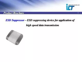
Transient Suppression • Constant advances in semiconductor process technologies make the design of protection very challenging. • Protection circuit must divert transient current and clamp transient voltage below the failure threshold of the protected
TVS (Transient Voltage Suppressor) v.s MLV ( Mutil-Layer Varistor ) Unidirection Bi-Direction MLV TVS
TVS v.s MLV Characteristics
Wireless Telecom ( Cell Phone / PDA ) MMC Interface SPE0511 , SPE0512 SPE0514 , SPE0515 LCD Screen SPE0511 , SPE0512 SPE0514 , SPE0515 Microphone SPE0511 , SPE0512 SPE0514 , SPE0515 USB SPE0511 , SPE0512 Bottom Connector SPE0511 , SPE0512 Earphone SPE0511 , SPE0512
DVD Player / STB IEEE 1394 ( Digital Interface ) SPE0504 , SPE0505 , SPE0506 USB SPE0511 , SPE0512 SPE0514 , SPE0515
DV / DSC LCD Screen SPE0511 , SPE0512 SPE0514 , SPE0515 Microphone SPE0511 , SPE0512 SPE0514 , SPE0515 LCD Screen SPE0511 , SPE0512 SPE0514 , SPE0515 MMC Interface SPE0511 , SPE0512 SPE0514 , SPE0515 USB SPE0511 , SPE0512
Motherboard / Notebook IEEE 1394 ( Digital Interface ) SPE0514 , SPE0515 SPE0504 . SPE0505 USB SPE0511 , SPE0512 IEEE 1284 ( Parallel interface ) SPE0514 , SPE0515 SPE0504 . SPE0505 MMC Interface SPE0511 , SPE0512 SPE0514 , SPE0515 PS2 SPE0511 , SPE0512