Download
1 / 31
310 likes | 327 Views
Learn about MEF 32 and its resiliency requirements for protecting Ethernet services across external interfaces. This presentation covers approved MEF specifications and key concepts for Carrier Ethernet services. Ideal for equipment manufacturers, service providers, and enterprise users.

E N D
Introducing the Specifications of the Metro Ethernet Forum MEF 32 Requirements for Service Protection Across External Interfaces
Agenda • Approved MEF Specifications • This presentation • About this Specification • In Scope / Out of Scope • Section Review • Summary
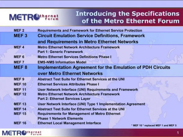
Approved MEF Specifications Note: MEF 1 and MEF 5 were superseded by MEF 10. MEF 6.1 supersedes MEF 6. MEF 10.2 supersedes MEF 10.1.1 MEF 10.1.1 supersedes MEF 10.1 MEF 10.1 Supersedes MEF 10. MEF 7 is superseded by MEF 7.1. MEF 22.1 supersedes MEF 22, MEF 23.1 supersedes MEF 23. MEF 26.1 supersedes MEF 26, 26.0.1,2,3.
MEF Specification Overview Requirements for Service Protection Across EIs – Phase 1 MEF 32 Purpose Identifies resiliency requirements at external interfaces applicable to MEF Service and associated Service End Points, which associate services with External Interfaces. Standardized Services Audience All, since they provide the fundamentals required to build devices and services that deliver Carrier Ethernet. For Enterprise users it gives the background to Service Level Specifications for Carrier Ethernet Services being offered by their Service Providers and helps to plan Ethernet Services as part of their overall network.
This Presentation • Purpose: • Introduction to MEF 32 • Highlights of MEF 32 requirements for Service Protection Across External Interfaces • Audience • Most importantly, Subscribers of Ethernet Services • Equipment Manufacturers supporting MEF 6.1 Services using Service Attributes defined in MEF 10.2 & MEF 10.2.1. • Service Providers supporting MEF 6.1 Services • Other Documents • Presentations of the other specifications and an overview of all specifications is available on the MEF web site • Other materials such as white papers and case studies are also available
Key Carrier Ethernet Definitions and Concepts Provides foundational definitions and concepts for Metro Ethernet Services, service attributes and parameter requirements and as well as traffic classification, traffic profiles and related recommendations to deliver Carrier Ethernet Services.
About the Specification • A resiliency mechanism needs to be robust enough to ensure a service is protected against various types of failures. • This specification contains requirements for protecting Ethernet Services at an External Interface against link or a Network Element (NE) failure. • It identifies resiliency requirements at external interfaces applicable to MEF Service and associated Service End Points, which associate services with External Interfaces.
In Scope • MEF 32 specifies requirements for Service protection across External Interfaces. The requirements for protection address only the Interconnection Zone : An Interconnection Zone is an area where External Interfaces are interconnecting two administrative domains • In scope of this specification for Phase I: • ENNI Interconnection Zone. • UNI Interconnection Zone.
Out of Scope • The following are out of scope of this specification for Phase I, but are candidates for inclusion in this document as future work items: • Requirements for UTA Service protection across ENNI Interconnection Zone. • Requirements for NID to MEN Interconnection Zone, when the NID is connected to the MEN over an EI. • Requirements for 1+1 protection scheme. • Failure detection time or degradation period is not included in the resiliency switching time (i.e. redirection time).
Definitions Networks are connected to each other at demarcation points. In many cases the resources supporting the connections, i.e., nodes and Link Connections (see definition below) are redundant, providing improved protection for Service • Service End Point (SEP) • Link Connection • Working Link Connection • Resilient Link Connection • Active and Standby Links Connections • Resiliency • Failure Event • Interconnected Zone
Service End Point • A Service End Point is an association of a service (EVC), • a service construct (OVC), • a UNI Tunnel Access (UTA) or a Virtual UNI (VUNI) to an External Interface (a UNI or ENNI in the context of this specification).
Link Connection • A “Link Connection” is defined in MEF 4, • denotes the connectivity supporting the exchange of Ethernet Service Frames or ENNI Frames as defined in MEF 10.2 and MEF 26 across an External Interface (EI). • Working Link Connection • designated Link Connection that exchanges Ethernet frames between Service End Points under normal condition • Resilient Link Connection • Link Connection is either pre-configured or automatically chosen to exchange Ethernet frames between Service End Points when the Working Link Connection fails.
Active and Standby Links Connections • A dynamic operational status of a pre-configured Link Connection indicating that the Link Connection is currently exchanging Ethernet Service frames or ENNI frames for specific Service End Points
Resiliency • Resiliency is a generic term covering both Protection and Restoration • Protection: re-establishing service delivery using pre-allocated resources. The pre-allocation of resources guarantees the re-establishment of the service. • Restoration: re-establishing service delivery using resources allocated at the time of need; This scheme does not pre-allocate resources, allowing them to be used during normal operation.
Failure Event • Any event that affects the performance of an Ethernet Service, violating the SLS agreement. Examples of such events are: link failure, NE failure, link degradation.
Interconnection Zone (I) • An Interconnection Zone is an area where External Interfaces are interconnecting two administrative domains, • contains a collection of domain border NEs of the two interconnected administrative domains, • associated with their respective External Interface and Link Connections connecting between the External Interfaces of two administrative domains and includes Link Connections connecting between the border domain NEs themselves, • can only be assigned to a single instance of the resiliency mechanism,
Interconnection Zone (II) • Interconnection Zones currently supported by MEF specifications are: UNI Interconnection Zone, between the subscriber domain and the Service Provider domain and ENNI Interconnection Zone, between two Service Providers
Reference Model • An Interconnection Zone may be defined between two interconnected networks supporting MEF defined ENNI External Interfaces or between a MEN and a subscriber premise supporting MEF defined UNI External Interfaces. • Several adjacent MENs for which protection requirements may be defined, are illustrated here:
General Requirements (I) Note: Highlights of MEF 32 requirements are provided. Please refer to the specification for comprehensive details. Resiliency Switching Mechanism The Ethernet physical layer as defined in MEF 10.2 [4] and MEF 26 [6] mustbe supported by the resiliency mechanism. • It must be able to operate at a UNI and ENNI, • It mustsupport resiliency per a single Service End Point, • It must always converge to a state such that the frames for a given Service End Point are carried on a single Link Connection,
General Requirements (II) • It must support traffic redirection caused by failure events, from the Working Link Connection to the Resilient Link Connection, in the Interconnection Zone without manual intervention, • It must provide indication of a protection state change to a Management System, i.e., which Link Connection has changed its Active or Standby status for each Service End Point, • It must provide indication of a protection state change to a Management System, i.e., which Link Connection has changed its Active or Standby status for each Service End Point, • It should be independent of other mechanisms inside the associated MEN and should be able to perform all its functionality independent of the internal functionality of the associated MEN…
General Requirements (III) • The resiliency Mechanism must provide indication of the protection state to the local associated networks in the Interconnection Zone. • In the absence of any other failure in the Interconnection Zone, the resiliency mechanism must be capable of protecting against any single failure within the Interconnection Zone (NE or Link Connection). • Each Service End Point must be supported by exactly one Working Link Connection and at least one Resilient Link Connection across the Interconnection Zone.
Requirements Addressing the Ethernet Layer • The resiliency mechanism must support Service Frames (comprising C-Tags, priority tag and untagged Ethernet frames) at the UNI reference point, as defined in the MEF 10.2, “Ethernet Services Attributes - Phase 2” [6], • It must support ENNI Frames, as well as L2CPs exchanged between the peering ENNI-N functions, as defined in the ENNI specification [6]. • It must NOT modify the Ethernet frames at the EI, however, it may add additional fields to the frames. In this case the FCS may be modified, • It should minimize the probability to negligible such that Ethernet Frames (unicast, multicast and broadcast frames) of a single Service End Point are not delivered more than once to the adjacent network beyond the Interconnection Zone.
Requirements Addressing Triggers for Recovery Actions • Requirements addressing operator manual commands • When a resilient Link Connection is pre-configured, the resiliency mechanism must support Operator manual commands to switch Service End Points from Active Link Connection to Standby Resilient Link Connection in the Interconnection Zone. • It must support the Lock command as defined in ITU-T Recommendation Y.1731 [9]. • Requirements Addressing Failure Events • The resiliency mechanism should be able to detect failures causing performance violations of the SLS (e.g., Link Connection failure) and switch the traffic from each affected Service End Point to a resilient Link Connection.
Requirements Addressing Configuration Aspects (I) • The resiliency mechanism must support the ability to manually map Service End Points to specific pre-configured Link Connections in the UNI Interconnection Zone. • The resiliency mechanism must support the ability to manually map Service End Points to specific pre-configured Link Connections in the ENNI Interconnection Zone. • The resiliency mechanism must support the ability to configure a Service End Point as 'unprotected'.
Requirements Addressing Configuration Aspects (II) • The resiliency mechanism must support a Management System's ability to retrieve the mapping configuration of Service End Points to Link Connections during normal and failure conditions in the Interconnection Zone. • It must support a Management System's ability to retrieve the protection state, as defined in [R9], of each Service End Point in the Interconnection Zone. • It must support the ability to operate in both Revertive and Non-Revertive Modes in the Interconnection Zone. • It must set Revertive Mode as the default mode per Service End Point in the Interconnection Zone, when one or more Protection Link Connections are configured. • It must have a configurable time to wait before reverting the traffic back to the repaired Working Connection Link, when one or more Protection Link Connections are configured.
Requirements Addressing Configuration Aspects (III) • The resiliency mechanism must have a configurable time to wait before reverting the traffic back to the repaired Working Connection Link, when one or more Protection Link Connections are configured. • It maysupport both Service End Points that operate in Revertive Mode together with other Service End Points that operate in Non-Revertive Mode in the same Link Connection in the Interconnection Zone. • It must support the ability to detect miss-configuration of Link Connections across an EI, in the Interconnection Zone. • And Manual traffic redirection switching should be hitless (i.e., zero frame loss).
Requirements For Scalability And Performance • The resiliency mechanism must support 4094 Service End Points in the UNI Interconnection Zone. • It must support at least 4094 Service End Points in the ENNI Interconnection Zone. • Automatic and manual traffic redirection between the Working Link Connection and a Resilient Link Connection in the Interconnection Zone must be performed in not more than 500 ms. • The Automatic and manual traffic redirection between the Working Link Connection and a Resilient Link Connection in the Interconnection Zone should be performed in not more than 250 ms.
Summary • In summary, MEF 32 identifies resiliency requirements at external interfaces applicable to MEF Service and associated Service End Points, which associate services with External Interfaces. MEF would like these requirements to be considered when designing a mechanism for Service Protection across an External Interface.
Accelerating Worldwide Adoption of Carrier-class Ethernet Networks and Services www.MetroEthernetForum.org