CCFL Backlighting Inverter Solution
Distributed By Rohm. CCFL Backlighting Inverter Solution. Golden Road Electronic Technology Co., Ltd. E1, 24F Zhao Feng Universe Building NO. 1800 Shanghai PRC WEB: www.goldenroad.com.cn TEL: 021-64401740 64401741 64401742 64401743 FAX: 021-64401629 64403212 Designed By: Colin (FAE)


CCFL Backlighting Inverter Solution
E N D
Presentation Transcript
Distributed By Rohm CCFL Backlighting Inverter Solution Golden Road Electronic Technology Co., Ltd. E1, 24F Zhao Feng Universe Building NO. 1800 Shanghai PRC WEB: www.goldenroad.com.cn TEL: 021-64401740 64401741 64401742 64401743 FAX: 021-64401629 64403212 Designed By: Colin (FAE) E-mail: colin.wang@goldenroad.com.cn jason.mai@goldenroad.com.cn Golden Road Electronic Co., Ltd.
Distributed By Rohm Rohm CCFL Control IC presentation High Performance PWM Controller Half Bridge Topologies for 1 lamp BD9883FV Half Bridge Topologies for 4 lampor above BD9884FV Golden Road Electronic Co., Ltd.
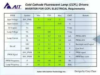
Distributed By Rohm 1 Lamp Solution LCD BACKLIGHT INVERTER DRIVE IC BD9883FV Features: High Efficiency Single Stage Power Conversion Half Bridge Topology And Reduce External Component Wide Input Voltage Rang From 6V To 30V Lamp Current and Voltage Feedback Control Soft Start Control & Dead Time Control Short Circuit Protection With Timer Latch Under Voltage Lock Out Analog And Burst Dimming Control PWM Control at Fixed Frequency ON / OFF Control SSOP-20 Package Golden Road Electronic Co., Ltd.
Distributed By Rohm • Descriptions • Designs for a CCFL inverter used in notebook or portable DVD player applications include small size, high efficiency and low cost. The BD9883FV provide the necessary function blocks to implement a highly efficient CCFL backlight inverter in a small footprint 20 SSOP package. It typically consumes less than 9mA of operating current, improving overall system efficiency. • External components count is minimized and system cost is reduced by integration such features as a feedback controlled PWM driver stage, the soft start, the lamp voltage and current feedback, the UVLO, The short circuit protection. It includes a shunt regulator, allowing it to operate with wide input voltage from 6.0~22V, supporting analog and burst dimming modes of operation. Standby function also reduces power dissipation. • The BD9883FV also provide lamp current and voltage sense feedback control circuit which it can protect the transformer from over voltage during start up or when an open lamp occurs. The transformer voltage is regulated with reducing duty circle when an over voltage is detected. The latter can be used to shut IC down when an open lamp condition continue more than a specific time. Golden Road Electronic Co., Ltd.
Distributed By Rohm 2 Schematic Diagram: Golden Road Electronic Co., Ltd.
Distributed By Rohm PIN Definition Golden Road Electronic Co., Ltd.
Distributed By Rohm Golden Road Electronic Co., Ltd.
Basic operation • 3.1 DUTY • Lamp intensity is controlled with the signal DUTY. There would be two kinds of dimming modes as below: • Analog dimming • Lamp intensity decrease from 100% to 0% when the DC voltage between 2.0V and 0.5V on DUTY pin. When voltage more than 2V on DUTY commands full brightness. • BURST dimming • Lamp intensity is controlled with signal DUTY. 2V on DUTY commands full brightness. The duty cycle of the burst dimming comparator determines the lamp brightness as a percent of rated lamp current. Distributed By Rohm Golden Road Electronic Co., Ltd.
3.2 BURST Oscillator Timing capacitor BCT is charged by the reference current source, and formed by the timing resistor BRT whose voltage is regulated at 1.25V. The saw-tooth waveform charges up to 2.0V, once reached, capacitors begin discharging down to 0.5V. Next timing capacitors start charging again and a new switching cycle begins. BRT would be recommended between 10 and 500k Ohm and BCT is from 0.001uF to 0.2uF. 3.3 Main Oscillator Timing capacitor CT is charged by the reference current source, formed by the timing resistor RT whose voltage is regulated at 1.25V. The saw-tooth waveform charges up to 2.0V, once reached, capacitors begin discharging down to 0.5V. Next timing capacitors start charging again and a new switching cycle begins. RT would be recommended between 10 and 150k Ohm and BCT is from 100pF to 1000pF. Distributed By Rohm Golden Road Electronic Co., Ltd.
3.4 SRT pin Operating Frequency setting pinuse an External resistor from SRT to RT for which adjusting the triangle oscillator. If you want to change the operating frequency when an open lamp occurs, please keep it unconnected. Otherwise, please connect a resistor between 80k to 500k Ohm to RT. 3.5 Control loop feedback This block includes lamp voltage loop and lamp current loop. The lamp voltage loop is consist of voltage detect pin Vs and the error output, The lamp current sense loop has little difference from the voltage one, both the lamp voltage and the current lamp are the most important feedback circuit of the IC. PWM output cycle is determined by FB, both Is and Vs are compared with the VREF, the output (FB) will compared with CT, then determine PWM output. Distributed By Rohm Golden Road Electronic Co., Ltd.
Distributed By Rohm The lamp current loop: Current feedback input pin detect the lamp current through a half rectifier circuit and a resistor, output compared with VREF (1.25V)which it is using an internal error amplifier to adjusting the PWM duty. In this loop, please must keep Is more than 0.4V, or the SRT will turn to LOW, SCP start to work, IC power off. FB will turn low when Is is high which is forced by an external signal. The lamp current loop gain will be determined by the reactive circuit which it is using a capacitor, connect to the error output for limiting loop gain and increase the frequency action. The capacitor between Is and FB range is from 1500pF to 10000pF. Golden Road Electronic Co., Ltd.
Distributed By Rohm The lamp voltage loop: Lamp current feedback input pin detect the lamp current through a half rectifier circuit and a resistor, output compared with VREF (1.25V)which it is using an internal error amplifier to adjusting the PWM duty. In this loop, more than 1.25V on Vs will make the overall system into protect stage. So please keep the voltage on Vs between 0.5v and 1V. The lamp voltage loop gain will be determined by the reactive circuit which it is using a capacitor, connect to the error output for limiting loop gain and increase the frequency action. The capacitor between Vs and FB range is from 1000pF to 4700pF. Golden Road Electronic Co., Ltd.
Distributed By Rohm 3.6 Soft Start The soft start function is provided that SS pin is connected through a capacitor to GND, a soft start circuit ensures a gradual increase in the input and output power. The capacitor connected to SS pin determines the rate of rise the duty ratio. It is charged by a current source of 1uA. 3.7 UVLO Under voltage lockout The under voltage lockout circuit guarantees stable operation of the IC’s control circuit by stopping and starting it as a function of the VIN value. The UVLO circuit turns on the control circuit when VIN exceeds 5.4V. When it is lower than 5.4V, the IC’s standby current is less than 10uA. Golden Road Electronic Co., Ltd.
Distributed By Rohm • 3.8 STB • Applying the higher voltage than 2V to STB pin enables the operation of the IC. Applying to the voltage than 0.7V to STB pin will disable the operation of the inverter. • 3.9 SCP • The short circuit protection function is to protect the overall system it is shorted. The capacitor connected to SCP pin determines the rate of the timer from system beginning to end when there is a short in output occurs. It is charged by a current source of 0.5uA. Golden Road Electronic Co., Ltd.
Distributed By Rohm Notes: CBD Golden Road Electronic Co., Ltd.
Distributed By Rohm CBD Golden Road Electronic Co., Ltd.
Distributed By Rohm CBD Golden Road Electronic Co., Ltd.
Distributed By Rohm CBD Golden Road Electronic Co., Ltd.