Tritium Control
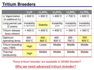
Tritium Control. A Major Issue for a Liquid Metal Blanket. Blanket modules. M LiPb. J 2. J 3. J FW. LiPb purification. h LiPb. Tritium extraction from LiPb. J 1. Pump. a Q PbLi. Q PbLi. air purification. Steam generator. J 4. J 5. h He. He purification. a Q He.

Tritium Control
E N D
Presentation Transcript
Tritium Control A Major Issue for a Liquid Metal Blanket Direction de l’Energie Nucléaire
Blanket modules MLiPb J2 J3 JFW LiPb purification hLiPb Tritium extraction from LiPb J1 Pump aQPbLi QPbLi air purification Steam generator J4 J5 hHe He purification aQHe Secondary circuit MHe QHe Blower Schematic Fluids Circulation in the Reactor Direction de l’Energie Nucléaire
J1 J3 J5 LiPb He J1 / J5 =140525 J2 J4 • J1 : Production rate • J2 : Extraction from LiPb hLiPb : extractor efficiency for LiPb Cout : Tritium output concentration in LiPb (mol m-3), GLiPb : LiPb flow rate (m3 s-1) • J3 : Permeation towards He coolant Cave : Tritium average concentration in LiPb (mol m-3) Kblanket: Blanket permeation factor (m3 s-1) • J4 : Extraction from He coolant GHe : He flow rate to detritiation unit (m3 s-1) • J5 : Release to environment LSG: Steam Generator leak flow (m3 s-1) ( J5 max = 1 g/year=27 Ci/day , ITER standard ) Analytical Model – Tritium Mass Balance Equations 1/2 Direction de l’Energie Nucléaire
Analytical Model – Tritium Mass Balance Equations 2/2 • A, s : respectively wall surface (m2) and wall thickness (m). Need to be evaluated for complex structures (see below) • Kssteel KsLiPb : Sievert constants (mol m-3 Pa-1/2), respectively in Eurofer and in LiPb • Dsteel Tritium diffusivity in Eurofer (m2 s-1) • PRFb is the Permeation Reduction Factor provided by permeation barrier (if any) Stationary results (*) : * Thanks to Italo Ricapito (ENEA consultant) who initiated these computations Direction de l’Energie Nucléaire
Materials and Temperature Coating Geometry Material factor : A Geometrical factor : s Coating : T concentration layering in LiPb : (not taken into account in this analytical model: convection) Computation of the Blanket Permeation Factor Direction de l’Energie Nucléaire
Ks0 (mol m-3 Pa-1/2) Ea (J mol-1) D0 (m2 s-1) Ea (J mol-1) LiPb 1.25 10-3 1350 4.03 10-8 19500 Eurofer 1.02 10-1 23810 1.22 10-7 14470 Materials factor computation • Significant permeation increase with temperature • Uncertainties when averaging temperatures Direction de l’Energie Nucléaire
N channels L e 2b 2p 2a Y(a, b, p, e) is the correction factor to be used to take into account the actual structure of the HCLL walls ? Geometrical factor computation • HCLL module is composed of many walls (FW, Stiffening grid, Cooling plates) where He circulates inside rectangular channels. • Permeation formula is relative to plain wall • How to adapt it to the actual wall structure ? • Lets A=2a.L.N (surface of He facing LiPb) • and s=e (minimum distance between He and LiPb). Direction de l’Energie Nucléaire
e b a p Problem identical to heat transfer by conduction • Temperature (K) tritium concentration (mol m-3) • Thermal diffusivity (m2 s-1) D.Ks,w / Ks,PbLi material factor (m2 s-1) • Heat flux (J s-1) tritium flow (mol s-1) LiPb He Direction de l’Energie Nucléaire
Correction Factor for Square Channels • The thicker the ratio e/a the larger the correction factor y Direction de l’Energie Nucléaire
a (mm) b (mm) e (mm) p (mm) y First Wall (LiPb side) 7.0 6.5 4.0 2.0 1.24 Stiffening plates 5.0 1.5 2.5 0.5 1.09 Cooling plates 2.25 2.25 1.0 0.95 1.31 Back plate NA NA 30.0 NA 1 Application to HCLL Walls • The three types of HCLL cooled walls have been modelled to derive their correction factor y Direction de l’Energie Nucléaire
LiPb facing He surface (m2) y.A / s (m) Percentage of total permeation First Wall (including side) 4.31 1336 1.06 Stiffening plates (including top and bottom) 37.06 16158 12.8 Cooling plates 82.94 108651 86.0 Back plate (plain) 4.0 133 0.1 Geometrical Factor Results for the HCLL Module • Module Kgeom= 126 278 m • 86 % of the permeation occurs through the cooling plates (and even more if we consider their higher temperature) Direction de l’Energie Nucléaire
Tritium flow towards He coolant (J3) • Kblanket = 0.89 / PRFb m3 s-1 (Tave = 480 °C, 260 modules) • hLiPb = 0.8 (reasonable efficiency for packed column extractor) • GLiPb limitation due to LiPb velocity (MHD pressure drops and corrosion) • Module hydraulic section for LiPb : 0.33 m2 • for whole blanket a VLiPb=1 mm/s n GLiPb =0.085 m3 s-1 = 790 kg s-1 Direction de l’Energie Nucléaire
a=0.08% 4.3 Ci/kg 43 Ci/kg Working Point • In existing He cooled fission reactor He leakage can be as high as 100% of the total inventory per year • assumption: He inventory=400 m3 = 2250 kg a LSG=1.63 Nm3/h • Tritium permeation through the SG is still to be evaluated. • present assumption : KSG=0 (optimistic ? Maybe not so much if HTO) Direction de l’Energie Nucléaire
Working point with He coolant contamination limit • The acceptable limit for the He contamination is sometimes reported to be 1Ci/kg = 10-7 kg of T per kg of He. Direction de l’Energie Nucléaire
Heat exchanger He + H2 + HT a = 0.08 % Oxidation bed Water Trap WaterTrap HCLL module H2O + HTO H2O + HTO gas / liquid column H2O 1000 ppm H2 100 ppm Chemical adjust Chemical adjust H2 0.1% He extraction LiPb He coolant Tritium extraction strategy • Oxidize the T in HTO (H2O injection in He coolant, oxidation bed for purge gas) • Extract tritiated water by zeolithe or cold trap • Advantages : develop natural oxide barriers both in blanket and in SG, much less permeation for HTO than for T2 • Drawbacks : release limit for HTO is 10 times more stringent than for T2 Direction de l’Energie Nucléaire
On going studies • Refinement of the blanket permeation flow computation (J3) • Finite elements modelling (conduction and convection of heat and of tritium concentration) • Local temperature, • LiPb flow (MHD, temperature convection, section variations, pressure drop), • Soret effect (permeation driven by temperature gradient) • Evaluate tritium permeation via the Steam Generator • Evaluate reasonable He leak rate for the whole coolant circuit • Evaluate the maximum He purification flow rate capability • If 4 x 50000 Nm3/h a no permeation barrier needed • Ensure the feasibility of the tritium extraction strategy aPower Plant Conceptual Study (model AB) Direction de l’Energie Nucléaire
Tritium production rate (at / cm3.neutron) 7,0E-03 6,0E-03 5,0E-03 4,0E-03 3,0E-03 2,0E-03 1,0E-03 0,0E+00 0 100 200 300 400 500 600 700 800 900 module radial dimension (mm) Possible 2D modelling of the HCLL module T diffusion and permeation via cas3m_fluid (heat-like) LiPb flow and T convection via cast3m_fluid Cin P Neutron code (Tripoli) Cout Thermal-mechanical code (cast3m) Direction de l’Energie Nucléaire