Download
1 / 41
440 likes | 753 Views
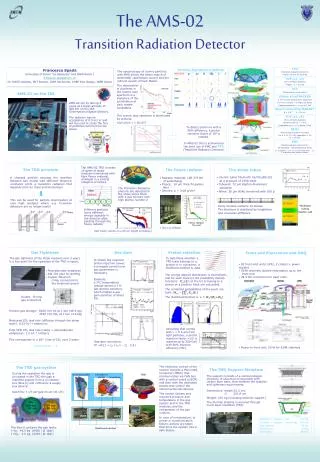
Optical Transition Radiation (OTR) Detectors for Beam Diagnostics. Vic Scarpine Instrumentation Department Accelerator Division Jan. 17, 2006. Outline. This is a general survey talk on OTR detectors for beam diagnostics Introduction What is OTR and why is it useful for beam diagnostics?

E N D
Optical Transition Radiation (OTR) Detectors for Beam Diagnostics Vic Scarpine Instrumentation Department Accelerator Division Jan. 17, 2006
Outline This is a general survey talk on OTR detectors for beam diagnostics • Introduction • What is OTR and why is it useful for beam diagnostics? • OTR detectors at other accelerators • OTR detectors at Fermilab • E-cool, A0, p/pbar transfer lines, Tevatron, Numi • Future applications of OTR for beamline diagnostics Accelerator Physics & Technology Seminar
Introduction What is Optical Transition Radiation? Optical Transition Radiation (OTR) is generated when a charged-particle beam transits the interface of two media with different dielectric constants, for example, vacuum to metal OTR detectors have been used with high energy and intensity electron beams CERN has tested OTR detection with proton beams and are using them extensively – Initial proton experiment at CERN-SPS in 1984 Accelerator Physics & Technology Seminar
OTR Emission Patterns Quantity of light proportional to foil reflectivity for reverse OTR Emission spectrum is very broad – signal in visible region Accelerator Physics & Technology Seminar
OTR Intensity Profile Accelerator Physics & Technology Seminar
Ray Diagram for OTR Imaging Accelerator Physics & Technology Seminar
OTR Detector Strategy • Convert particle beam information to optical radiation and then use COT imaging technology to acquire beam information • Use thin foil to minimize beam scattering • Beam image provides 2-D information on: • Transverse profile and shape (tilt) • Transverse position • Emittance • Intensity • Divergence, energy, bunch length, longitudinal profile… Accelerator Physics & Technology Seminar
OTR Detectors for Beam Diagnostics • OTR detectors are a primary beam diagnostics tool at many accelerators – mostly electron machines • Quick search of JACoW (Joint Accelerator Conference Website) for titles with “optical transition radiation” produces 173 papers. • OTR detectors used at: • Argonne APS, Los Alamos FEL, Jefferson Lab, Beijing FEL, BESSY FEL, Final Focus Test Beam at SLAC, Tesla Test Facility, ELETTRA Linac, Linac Coherent Light Source FEL, Fermilab, CERN SPS, etc • To numerous to discuss them all… Accelerator Physics & Technology Seminar
First OTR Detection for Electron Beams (1975) 40-60 MeV electrons Accelerator Physics & Technology Seminar
Two-Foil Interferometry Two-foil interferometry for electron beams to measure energy and beam divergence • Energy from positions of interference peaks • Divergence from modulation of interference pattern Accelerator Physics & Technology Seminar
Two-Foil Interferometry Accelerator Physics & Technology Seminar
High Power Beam Profile OTR Monitor at CEBAF • High power beam – 800 kW • 0.8 to 4 GeV electron energy • Forward OTR from 0.25 m carbon foil • Independent of reflectivity of C • Small beam size ~ 100 m Accelerator Physics & Technology Seminar
OTR Emission for Small Beams • Issue of measuring the small beam profiles – what is limiting resolution? • Is there a lg uncertainty in OTR photon emission position? • This detector measures 100 m rms size of a 3.2 GeV beam - lg is 3.2 mm • Standard optical diffraction seems to limit OTR resolution up to very high g Accelerator Physics & Technology Seminar
OTR Detectors for E-cool • OTR monitors are being used with pulsed beam to image and model the charge distributions of the 4.3 MeV electron beam used in the electron cooler at Fermilab. • A. Warner, A. Burov, K. Carlson, G. Kazakevich, S. Nagaitsev, L.Prost, M. Sutherland, and M. Tiunov • Highly-reflective 2 inch-diameter 5 µm aluminum OTR-screen • The measurements are done in a pulse-signal mode in the beam current range of 0.03-0.8 A and at pulse durations ranging from 1 µs to 4 µs. Accelerator Physics & Technology Seminar
E-cool OTR Linearity • The dependence of the integral of detected light in the beam spot versus the beam current • Shows good linearity of the OTR monitor. Accelerator Physics & Technology Seminar
E-cool OTR Profile Measurements • X and Y beam profiles versus current in lens SPA06 Accelerator Physics & Technology Seminar
E-cool Beam Optics Simulations Beam profiles can not be explained as a trivial effect of focusing with SPA06 lens. Simulations of the beam optics in DC mode from the cathode to the OTR monitor with space charge effects included. Measured rescaled (dots) and calculated (solid lines) beam profiles for the SPA06 current values of 6 A (blue color), 14 A (red color), and 22 A (green color). Accelerator Physics & Technology Seminar
OTR Detectors at A0 Accelerator Physics & Technology Seminar
Plasma Focusing of Electron Beam Accelerator Physics & Technology Seminar
Working being done by Gregory Kazakevitch to measure beam energy OTR Interferometry at A0 I and II are OTR screens. The electron passing through OTR I radiates due to interaction with the screen II the photon-II, which interferes with the photon-I reflected from screen II. The phase shift one can express as: Here f1 and f2 phases of the photon-I and photon-II respectively. Accelerator Physics & Technology Seminar
Interference Patterns Calculated interference patterns for g = 30 and g = 30.5 electron beams The interference method allows to separate the difference in the energy of the electrons and also is applicable to the emittance measurements. Accelerator Physics & Technology Seminar
OTR Detectors for Fermilab Proton and Antiproton Beams • Will OTR detectors work for Fermilab transfer lines? • Compare to electron machines to determine feasibility for FNAL Accelerator Physics & Technology Seminar
Prototype OTR Location – AP1 Line • Fairly frequent access to location • Location immediately available • Frequent beam- stacking • High intensity – 4e12 • High energy – 120 GeV • 1/g -> 8 milliradians • Beam size of 1s ~ 1 mm • High radiation environment? ~ 6 krad/wk at 1 meter Accelerator Physics & Technology Seminar
Prototype OTR Block Diagram Accelerator Physics & Technology Seminar
Prototype OTR Block Diagram Accelerator Physics & Technology Seminar
Images with 12 m Titanium Foil • Proton intensity ~4.5e12 • Using x0.005 light attenuator • Measurements down to ~ 5e9 possible for same beam size and same g Accelerator Physics & Technology Seminar
Change Beam Size Vertical beam size reduced by x2 and tracked by OTR detector Accelerator Physics & Technology Seminar
OTR with 20 m Aluminum Foil • ~4.7e12 protons • x0.001 light attenuation • Image show some structure but need to determine if it beam or foil induced Accelerator Physics & Technology Seminar
An OTR Detector for Fermilab Proton and Antoproton Beamlines • Develop an OTR detector as part of the Run II upgrade program and as part of the NuMI primary beam line - design for high g (> ~100) Accelerator Physics & Technology Seminar
OTR Detectors for A150 Line • Two OTR detectors in low dispersion region to measure emittance • Third OTR detector to measure pbar beam shape into Tevatron • Two of three OTR detectors next to multiwires Accelerator Physics & Technology Seminar
Diagram of OTR detector • Radiation hardened CID camera • Near field/far field focusing • Neutral density filter wheels with polarizers • Bidirectional beam measurements with selectable foils • Vacuum certified to few 10-9 Accelerator Physics & Technology Seminar
Constructed OTR Detector • 5 m mylar with 1200 angstroms Aluminum • Back illuminated fiducials for in-situ calibration Accelerator Physics & Technology Seminar
OTR Installed in Tevatron • Installed at E0 next to new IPM • Used for single turn injection studies • Proton and pbar foils Accelerator Physics & Technology Seminar
Foils Damage The left photograph is of a 3 mil thick titanium vacuum window exposed to over 1020 120 GeV protons. The center photograph is a similar vacuum window exposed to ~3x10¹⁸ 120 GeV protons but with a smaller beam spot size. The right photograph is of our prototype OTR 20 mm aluminum foil exposed to ~1019 120 GeV protons with a larger beam spot size. Titanium has higher melting point but darkens and has more scatter Accelerator Physics & Technology Seminar
OTR Detectors at CERN • Jung, Ferioli, et al pursuing OTR detectors for many CERN transport lines: • The first (4 OTRs with 12 microns Ti and 25 microns Al/Mylar foils) have been installed in 1998-99 to show beam profiles from PS and injected into the SPS ring at an energy of 26 GeV. • In 2000 they installed 2 OTR (Ti foils) in the SPS ring to measure matching parameters of the circulating beam. • In 2003 they installed 11 OTRs (Ti foils) in the extraction line of SPS and injection LHC line (TI8) to observe 450 GeV beams. • In 2005 they are installing 7 OTRs in the CNGC line (for the Gran Sasso neutrino experiments). • In 2006-7 they will install 5 OTRs in the TI8 beamline and ~13 OTRs in the new beamline between SPS and LHC. • By 2007 they will have about 42 working OTRs. Accelerator Physics & Technology Seminar
OTR Detectors at CERN CERN builds their OTR detectors with many screen options Accelerator Physics & Technology Seminar
Fast Profile Acquisition at CERN • Fast OTR profiles can be acquired using fast digitizing cameras with or without MCP intensifier/shutter • Can be used for turn-by-turn or beam time structure • Sequence below taken with MCP gated camera at rate of 10 kHz Accelerator Physics & Technology Seminar
OTR Detectors for the Future • From ILC Diagnostic Summary for working group T9… “From the point of view of the LC design, it is clear that there are fundamental beam size monitor performance questions that must be addressed with R&D.” Pasquinelli and Ross, 2001 “…promising new technology: 1) Optical Transition Radiation has been used to image beams below 10 mm at the KEK-ATF…” • From ILC website, Baseline Configuration Document, Instrumentation and Controls section: “Beam Profile Monitor System (Transverse) Laserwire, etc” Accelerator Physics & Technology Seminar
Optical Diffraction Radiation (ODR) Like OTR but using a non-intercepting target Calculated Measured Accelerator Physics & Technology Seminar