HYDRAULICS & PNEUMATICS
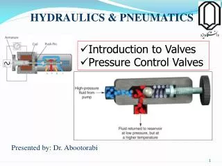
HYDRAULICS & PNEUMATICS. Introduction to Valves Pressure Control Valves. Presented by: Dr. Abootorabi. Primary Control Functions in a Hydraulic System.

HYDRAULICS & PNEUMATICS
E N D
Presentation Transcript
HYDRAULICS & PNEUMATICS • Introduction to Valves • Pressure Control Valves Presented by: Dr. Abootorabi
Primary Control Functions in a Hydraulic System • Control valves allow hydraulic systems to produce the type of motion or level of force needed to complete the functions expected of a hydraulic circuit. • A variety of valves can control actuator direction, speed, and force output.
Primary Control Functions in a Hydraulic System • The three basic types of control valves are: • Pressure control • Directional control • Flow control
Primary Control Functions in a Hydraulic System • Pressure control valves can: • Protect the system from damage due to excessive pressure • Sequence motion • Limit pressure in selected sections of a circuit
Primary Control Functions in a Hydraulic System • A system pressure control valve
Primary Control Functions in a Hydraulic System • Directional control valves direct fluid flow to establish and control actuator movement .
Primary Control Functions in a Hydraulic System • Flow control valves control the operating speed of actuators • They provide a means to vary the rate of fluid flow
Actuating force • With some types of poppet valves, the actuating force, which is dependent on pressure and area, may be very high. In order to avoid this, pressure compensation may be provided at the valves.
Poppet principle • Valves are based either on the poppet principle or slide principle. In poppet valves, a ball, a cone or a disc is pressed by a spring against the seat of a passage. Valves of this kind provide a very efficient seal. The illustration shows a cone used as a sealing element.
Slide principle • This illustration shows the principle of a longitudinal slide valve. In order to allow the piston to move, it has a certain clearance and floats in hydraulic fluids. Ring grooves ensure an even film of oil and thus pressureequilibrium. The piston can thus be moved with minimal frictional losses. • This type of valve cannot provide a perfect seal, which means that there is always a certain oil leakage.
Piston overlap • The switching characteristics of a valve are governed by, among other things, its piston overlap. A distinction is made between positive, negative and zero overlap. In the case of positive overlap, the port in question is completely covered by the piston, while with negative overlap it is less than completely covered. In the case of zero overlap, the distances between the control edges of the piston and of the port are exactly the same.
Negative switching overlap • In the case of negative overlap, flow from A to T is not quite closed when the inlet P is opened. This means that the pressure at port A rises slowly and the piston starts gently. • In manufacturers' data sheets, overlap positions are shown within dotted lines between the switching positions, or the overlap positions are shown in color.
Positive switching overlap • In the case of positive overlap, the left-hand piston does not open the passage from P to A until the tank has been completely isolated by the other piston. Pressure is immediately fed to the load device (cylinder or hydraulic motor) with the result that this starts abruptly.
Basic Structure and Features of Control Valves • A spool is a cylindrical metal piece fitted into the bore of a valve body. • The spool is used to block or direct fluid through a valve to produce a desired fluid flow characteristic.
Basic Structure and Features of Control Valves • Internal and external forces are used to position the various valve elements: • Springs and pilot pressure are typical internal forces used to operate valve elements • Manual, pilot pressure, and electromagnetic force are common external forces used for operation
Basic Structure and Features of Control Valves • Normal valve position refers to the position the internal elements assume when a hydraulic system is shut down: • Normally open • Normally closed
Valve Operation and Springs, Fluid Pressure, and Fluid Flow • Springs, fluid pressure, and fluid flow are very important in the operation of hydraulic system control valves. • Springs are used in control valves to: • Move spools and other internal elements • Establish the maximum operating pressure • Serve as a biasing force
Valve Operation and Springs, Fluid Pressure, and Fluid Flow • Common uses for springs
Valve Operation and Springs, Fluid Pressure, and Fluid Flow • Fluid pressure is used in control valves to: • Directly open or close valves • Remotely operate a valve element • Operate a compensating device to obtain desired fluid flow
Valve Operation and Springs, Fluid Pressure, and Fluid Flow • Fluid flow through an orifice is used in control valves to establish differences in pressure. • These pressure differences combined with balancing pistons and biasing springs are commonly used in the operation of pressure and flow control valves.
Pressure Control Devices • Pressure control valves may be grouped into one of five types: • System maximum pressure control • Actuator sequence control • Restrained movement control • Pump unloading control • Reduced pressure control
Pressure Control Devices • Maximum system pressure control devices are referred to as: • Relief valves • Safety valves • Hydraulic pressure fuses
Pressure Control Devices • Relief valves are normally closed valves. • They open when system pressure approaches the set maximum operating pressure. • The operation of relief valves can be classified as: • Direct operated • Balancing piston (compound or pilot-opereted)
Pressure Control Devices • Direct-operated relief valves use system pressure to generate force to compress a spring. • This opens a ball or poppet valve, allowing excess fluid to return to the reservoir.
Pressure Control Devices • Direct-operated relief valve
Pressure Control Devices • Compound relief valves consist of pilot- and balancing-piston sections: • Combined into a single valve • More efficient and quieter than direct-operated relief valves
Pressure Control Devices • Typical compound relief valve
Pressure Control Devices • The pilot section of the compound relief valve contains a small, direct-operated relief valve. • The pilot section indirectly establishes maximum system pressure by controlling the pressure in the balancing-piston section of the valve.
Pressure Control Devices • The balancing-piston section of the compound relief valve uses a metering orifice and a balancing spring to create pressure and force differences. • These differences correctly position the piston to produce a desired maximum system operating pressure.
Pressure Control Devices • Compound pressure relief valves are designed to accommodate higher pressures than direct acting relief valves at the same flow rate capacity.
Pressure Control Devices • Compound relief valves can also have the outlet port. Outlet port
Pressure Control Devices • Compound relief valves can also be operated remotely by using the outlet port from the chamber above the piston.
Pressure Control Devices • This chamber in turn can be vented to the tank through a solenoid-operated direction control valve.
Pressure Control Devices • Cracking pressure: The point at which the internal pressure of a hydraulic system triggers or actuates a valve. Also called the blow-off pressure. • Full-flow pressure: The point at which a relief valve is diverting flow at its maximumrate.
Pressure Control Devices • Pressure override: The full-flow pressure minus the cracking pressure. The pressure override is a measure of the increase in pressure over the cracking pressure when additional flow passes through the valve after it cracks.
Pressure Control Devices • The application of two direct-operated relief valves for Cushioning of Hydraulic Motor:
Pressure Control Devices • Safety valves are used to prevent damage to the hydraulic system if the system relief valve should fail to open. • Typically, safety valves are direct-operated relief valves. • Safety valves are generally set 25% higher than the normal system operating pressure.
Pressure Control Devices • Hydraulic pressure fuses function as a pressure-limiting device by using a disk that ruptures at a predetermined pressure. • They act as a positive-pressure-limiting device for systems where system pressure limits are critical to safe system operation.
Pressure Control Devices • A typical hydraulic pressure fuse
Pressure Control Devices • Sequence valves allow the automatic sequencing of two or more actuators in a hydraulic circuit • Primary actuator moves as soon as fluid flow is directed to the actuator section of the circuit • Sequence valve blocks flow to the secondary actuator until a predetermined pressure is reached, then allows fluid flow to the actuator
Pressure Control Devices • A sequence valve is typically fitted with an integral check (non-return) valve. • This allows free flow of fluid around the valve when the direction of the actuator is reversed.
Pressure Control Devices • A circuit containing a sequence valve
Pressure Control Devices • Restrained movement control valves are used in circuits to prevent unexpected actuator movement. Often called: • Counterbalance (back pressure) valves when used with cylinders • Brake valves when used with motors
Pressure Control Devices • Counterbalance valves prevent unexpected lowering of the boom.
Pressure Control Devices • Counterbalance and brake valves are normally closed valves. • A check valve is required to permit free reverse flow around to valve. • Counterbalance valves allow the downward movement of loads supported by a cylinder only when the system pump is operating. • Force generated by system pressure and the force created by the weight of the load are needed to move the load downward.
Pressure Control Devices • Circuit containing a counterbalance valve
Pressure Control Devices • Brake valves are used to prevent an overrunning load from continuing to turn a hydraulic motor after the directional control valve has been closed. • Overrunning loads can turn the motor into a pump, allowing the motor to turn past selected point.
Pressure Control Devices • Circuit containing a brake valve
Pressure Control Devices • Pump unloading controls hold a desired operating pressure while the pump operates at near-zeropressure. This reduces energy consumption and maintenance costs. Unloading valves are normally closed valves with external pilots. • Pump unloading controls use an unloading valve and a dualpump or accumulator to maintain desired system pressure while dumping unneeded pump output to the reservoir at very low pressure.
Pressure Control Devices • Circuit containing an unloading relief valve (using accumulator)