Download

1 / 1
20 likes | 216 Views
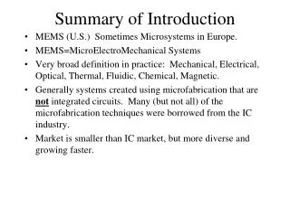
Critical Heat Flux of Nanofluids Questar III New Visions Math Engineering Technology & Science Program through the kind leadership of Dr. Theo Borca- Tascuic at Rensselaer Polytechnic Institute. ABSTRACT. MATERIALS AND METHODS. RESULTS. Figure 3: Heat Flux Example Curve.

E N D
Critical Heat Flux of Nanofluids Questar III New Visions Math Engineering Technology & Science Program through the kind leadership of Dr. Theo Borca-Tascuic at Rensselaer Polytechnic Institute ABSTRACT MATERIALS AND METHODS RESULTS Figure 3: Heat Flux Example Curve When a system reaches the condition of critical heat flux, the system’s cooling liquid can no longer efficiently transfer heat away from the hot surface. Traditional liquids used in cooling applications are limited by reaching critical heat flux conditions at temperatures that are too low for today’s technologies. As such, researchers are looking into the use of nanofluids as coolants. Our testing of the heat fluxes focused on 0.05% solutions of TiO2 nanoparticles, Al2O3nanoparticles, and various ratios of the two. The data indicated that these nanofluids caused a significant increase in critical heat flux, compared to deionized water alone. Also, critical heat flux increased as the ratio of TiO2 to Al2O3 increased, providing a solid foundation for future research. Summary: For the experiment, different nanofluids were tested for their CHF. We sought the maximum CHF for a 0.05% solution of aluminum oxide (Al2O3), titanium dioxide (TiO2), or a certain mixture of the two when suspended in distilled water. For each solution, we measured the surface area of the wire (A), the initial temperature of the fluid (we assumed this was also the initial temperature of the wire, T), and the voltage traveling through the wire (V), as we gradually increased the voltage. By putting the wire in series with a known resistor, we were able to calculate the current (I), resistance (R), power (P), and heat flux (HF) of the wire. Using the temperature coefficient of resistance (a), the temperature of the wire was calculated. See Figure 1A. Procedure: The experimental setup consisted of a glass apparatus containing a wire that could be submerged in liquid (Figure 2), hardware, and software. A nichromewire was placed across two contacts and held in place by caps. A caliper was used to measure the length of the wire. The wire was then submerged in the test solution. The solutions were prepared with 0.05% volume concentration of nanofluid in 300 mL of distilled water. Solutions of two materials, TiO2 and Al2O3, were tested alone and in mixtures of varying ratios. The apparatus was placed on a hot plate and heated to 99 oC. A LabViewprogram was used in conjunction with an Agilent 34970A data acquisition unit to increase the voltage going through the heater wire every 30 seconds. This change in voltage was used to control the heating rate of the wire. Critical heat flux is reached when the heat flux no longer increases with the rise in temperature or the wire breaks from the large temperature change (as shown in Figure 3). Point A: Critical heat flux (CHF) Point B: Point when wire breaks A B Figure 1: Relevant equations used V= IR to calculate current (I, in amps) for known resistor in series with wire, thus for all of circuit P = VI to calculate power (P, in watts) going through the wire HF = P/A to calculate heat flux in watts/square meter of surface area of the wire V = IR to calculate resistance of wire (R in ohms) as voltage and current changed DR/R0= aDT to calculate temperature of wire (T, in oC) as the resistance varied. Wire temperature could not be measured directly without affecting the data. INTRODUCTION • Critical Heat Flux (CHF): The critical heat flux (CHF) is the point where boiling of a liquid creates a gas film on the heating surface so that it can no longer be cooled by the liquid. A low CHF can deteriorate the stability of a system, while a high CHF can increase the safety and economic competitiveness of a system and its components. • Nanofluids: A nanofluid is a fluid with particles on the nanometer scale suspended in a solution (water or oil). These solutions have much higher and stronger temperature dependent thermal conductivities than traditional fluids. • Why We Should Care: • Previous research shows that nanofluids effectively cool heated surfaces. It is theorized that nanoparticles adhere to heated surfaces, creating a small layer of insulation on the heated surface. This insulation appears to be very important in changing the critical heat flux of cooling systems. If a cooling system can run at a higher temperature and be more effective, then the cost of the nanofluid can be offset by the increased system productivity. It is predicted that nanofluids will be useful in electronic cooling as well as in the cooling systems of nuclear and fossil fuel power plants. DI H2O Al2O3 TiO2 * This test exceeded the voltage output of the hardware; the true vCHFalue exceeds what is reported CONCLUSIONS • A 0.05% concentration with a 1:3 ratio of Al2O3 to TiO2 had the highest critical heat flux at 5.1 MW/m2. • During the initial tests some water boiled off, resulting in a change in concentration and burned out wires. We repeated the tests but reduced the fluid temperature to 99°C and added water to compensate for boil off, which allowed for more consistent results. • Nanofluids allow materials to endure higher temperatures before reaching their critical heat flux. In future tests, we would test different concentrations other than 0.05% and greater ratios than 1:3 of Al2O3 to TiO2. Figure 2 : Testing Apparatus. The glowing wire indicates critical heat flux is reached. CITATIONS ACKNOWLEDGEMENTS De Leon, Omar; Wong, Kaufui. Applications of Nanofluids. 24 November 2009. Web. 9 November 2011. • Frosell, James. Determination of the Critical Heat Flux of Nanofluid Solutions. Web. 9 November 2011 “Nanofluids”. web.mit.edu. np. nd. Web. 9 November 2011 A special thanks to Dr. Theo Borca-Tasciuc and his group for allowing us to work in the lab. Also, special thanks to Mr. Liang Hun, Mr. Mehmed “Sitki” Ulcay and JaronKuppers for assisting us during the experiment.