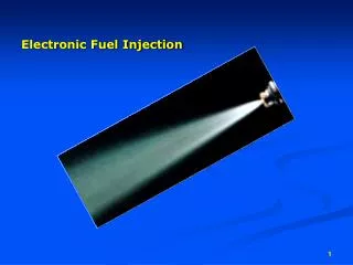
FUEL INJECTION IN THE SPARK IGNITION ENGINE
510 likes | 862 Views
FUEL INJECTION IN THE SPARK IGNITION ENGINE. Merits of Fuel Injection in the SI Engine. Absence of Venturi – No Restriction in Air Flow/Higher Vol. Eff./Torque/Power Hot Spots for Preheating cold air eliminated/Denser air enters

FUEL INJECTION IN THE SPARK IGNITION ENGINE
E N D
Presentation Transcript
Merits of Fuel Injection in the SI Engine • Absence of Venturi – No Restriction in Air Flow/Higher Vol. Eff./Torque/Power • Hot Spots for Preheating cold air eliminated/Denser air enters • Manifold Branch Pipes Not concerned with Mixture Preparation (MPI) • Better Acceleration Response (MPI) • Fuel Atomization Generally Improved
Merits (Continued) • Use of Greater Valve Overlap • Use of Sensors to Monitor Operating Parameters/Gives Accurate Matching of Air/fuel Requirements: Improves Power, Reduces fuel consumption and Emissions • Precise in Metering Fuel in Ports • Precise Fuel Distribution Between Cylinders (MPI)
Merits (Continued) • Fuel Transportation in Manifold not required (MPI) so no Wall Wetting • Fuel Surge During Fast Cornering or Heavy Braking Eliminated • Adaptable and Suitable For Supercharging (SPI and MPI)
Limitations of Petrol Injection • High Initial Cost/High Replacement Cost • Increased Care and Attention/More Servicing Problems • Requires Special Servicing Equipment to Diagnose Faults and Failures • Special Knowledge of Mechanical and Electrical Systems Needed to Diagnose and Rectify Faults
Limitations of Petrol Injection (Continued) • Injection Equipment Complicated, Delicate to Handle and Impossible to Service by Roadside Service Units • Contain More Mechanical and Electrical Components Which May Go Wrong • Increased Hydraulic and Mechanical Noise Due to Pumping and Metering of Fuel
Limitations of Petrol Injection (Continued) • Very Careful Filtration Needed Due to Fine Tolerances of Metering and Discharging Components • More Electrical/Mechanical Power Needed to Drive Fuel Pump and/or Injection Devices • More Fuel Pumping/Injection Equip-ment and Pipe Plumbing Required- May be Awkwardly Placed and Bulky
Indirect Injection • Also Called Manifold Injection or Single Point Injection (SPI) or Throttle Body Injection (TBI) • Injector Usually Upstream From Throttle (Air Intake Side) or In Some Cases Placed on the Opposite Side • Pressures are Low – 2 to 6 Bar. Maybe Injected Irrespective of Intake Process • Cost Would be Low
Indirect Injection (Continued) • Has Same Air and Fuel Mixing and Distribution Problems as Carburetor but Without Venturi Restriction so Gives Higher Engine Volumetric Efficiency • Higher Injection Pressures Compared to Carburetion – Speeds up Atomization of Liquid Fuel
Semi-direct Injection • Also Called Port Injection or Indirect Multipoint Injection (IMPI) or Simply Multi-point Injection (MPI) • Injectors Positioned in Each Induction Manifold Branch Just in Front of Inlet Port • Injection at Low Pressure (2-6 Bar) • Need Not Be Synchronized With Engine Induction Cycle
Semi-direct Injection (Continued) • Fuel Can Be Discharged Simultaneously to Each Induction Pipe Where it is Mixed and Stored Until IVO • Need Not Be Timed – Requires Low Discharge Pressures – Injectors Not Exposed to Combustion Products so Complexity Reduced – Less Cost
Semi-direct Injection (Continued) • No Fuel Distribution Difficulties Since Each Injector Discharges Directly Into Its Own Port and Mixture Moves a Short Distance Before Entering Cylinder • Induction Manifold Deals Mainly With Only Inducted Air – So Branch Pipes Can Be Enlarged and Extended to Maximize Ram Effect
Direct Cylinder Injection • Also Called Direct Multi-point Injection (DMPI) or Gasoline Direct Injection (GDI) • Injection May be During Intake or Compression Process • Increased Turbulence Required • To Compensate For Shorter Permitted Time For Injection/Atomization/Mixing Injection Pressure Must Be Higher
Direct Cylinder Injection (Continued) • More Valve Overlap Possible So Fresh Air Can Be Utilized For Scavenging • Injector Nozzle Must Be Designed For Higher Pressure and Temperature So Must Be More Robust and Will Be Costlier Than Other Types • Position and Direction of Injection Are Important – No One Position Will Be Ideal For All Operating Conditions
Direct Cylinder Injection (Continued) • Air and Fuel Mixing Is More Thorough in Large Cylinders Than In Small Cylinders Because Droplet Size is the Same • Condensation and Wall Wetting in Intake Manifold Eliminated But Condensation On Piston Crown and Cylinder Walls
Major Features With Petrol Injection • There is Separate Air and Fuel Metering • Fuel Metering is Precise Under All Engine Operating Conditions
Methods of Discharging Fuel Into Air • CONTINUOUS INJECTION Injector Nozzle and Valve are Permanently Open While Engine is Operating Amount of Fuel Discharged as a Spray is Controlled by • Varying Metering Orifice, or • Varying Fuel Discharge Pressure, or • Both
Methods of Discharging Fuel Into Air (Continued) 2. INTERMITTENT OR PULSED INJECTION Fuel is Sprayed at Regular Intervals With Constant Fuel Discharge Pressure Amount of Fuel Discharged is Controlled By the Time Period the Injector Nozzle Valve is Open
Comparing Pulsed and Continuous Injection Assume Engine Operates Between 750 (Idling) and 7500 rev/min (Max. Speed) (1:10 ratio) In Continuous Fuel Injection: • Fuel Flow has to vary by a Factor of 1:50 by Volume using Variable Area Orifice • Injection Pressure has to Vary by a Factor of 1:2500 using Fixed Orifice Or a Combination of Both Variables
Comparing Pulsed and Continuous Injection (Continued) In Pulsed Fuel Injection: • Nozzle Valve is Opened For a Short Time When Fuel Has to Be Sprayed • Fuel Flow Has to Vary by a Factor of 1:5 (Between Idle and Maximum Speed) • This Range is Increased Significantly For Cold Starting Where Control Accuracy Requirement is Much Reduced
Types of Injection For MPI • Timed Injection Start of Fuel Delivery For Each Cylinder Occurs at the Same Angular Point in Engine Cycle – Could be 60 or 90 Deg. ATDC of Induction Stroke of Each Cyl. • Non-timed Injection All Injectors Programmed to Discharge Fuel at Same Time. Each Piston Will be on a Different Part of the Cycle
Operation • Injection System Must Sense Changes to Influencing Parameters • Pass Information to a Coordinating System (Microprocessor or Computer) • Which In Turn Integrates Individual Signals and Interprets Fuel Requirements • Then Signals Injector to Open and Close
Operation (Continued) • Needs are Transmitted by Mechanical, Hydraulic or Electrical Means to Pumping and Metering Devices Which Supply Correct Quantity of Fuel to the Appropriate Injector
Controlling Parameters to Sense(Some of the Parameters) • Engine Speed • Amount of Inlet Air (Engine Load) • Throttle Position • Air Temperature • Coolant Temperature • Altitude • Cranking Speed • Exhaust Oxygen Concentration • Battery Voltage
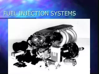
Gasoline Fuel Injection System Components • Electric Fuel Pump • Fuel Accumulator – Maintains Fuel Line Pressure When Engine is Shut Off and Quietens the Noise Created by the Roller Cell Pump • Fuel Filter - A Pleated Paper or Lint-of-fluff Type Plus Strainer • Primary Pressure Regulator – Maintains Output Delivery Pressure to be About 5 Bar
Gasoline Fuel Injection System Components (Continued) • Push Up Valve – Prevents Control Pressure Circuit Leakage. It is a Non-return Valve Placed at Opposite End of Pressure Regulator • Fuel Injection Valve – Valves are Insulated in Holders to Prevent Fuel Vapor Bubbles Forming in the Fuel Lines Due to Engine Heat. Valves Open at about 3.3 Bar and Spray Fuel. Valve Oscillates About 1500 cycles per second and so Helps in Atomization
K-Jetronic Fuel Injection System (F.I.S.) (Bosch) This is a Driverless Mechanical F.I.S. Fuel is Continuously Metered in Proportion to Quantity of Air Induced into Engine Cylinders “K” Stands for the German Word for “Continuously”
K-Jetronic Fuel Injection System (F.I.S.) (Bosch) (Continued) Considered in 3 Parts • Air Flow Measurement 2. Fuel Supply 3. Metering and Injection of Fuel
K-Jetronic Fuel Injection System (F.I.S.) (Bosch) (Continued) • Air Flow Sensor Measures the Throttle Controlled Quantity of Air Drawn into the Engine • Pressurized Fuel Provided by an Electric Motor Driven Roller-type Pump Which Delivers Fuel Through an Accumulator and Filter to the Mixture Control Distributor Unit. A Pressure Regulator Maintains the Fuel Entering the Mixture Control Unit at Constant Pressure
K-Jetronic Fuel Injection System (F.I.S.) (Bosch) (Continued) 3. Amount of Fuel Discharged into Air is Related to Measured Air Flow Signaled to Mixture Controlled Unit Whose Function is to Meter Corresponding Quantity of Fuel Transferred to Injector