
Impact of Shock Absorbing Mechanism on Forces in Cross-Country Ski Poles
This study examines the effectiveness of a shock-absorbing spring mechanism inserted into Nordic ski poles to reduce peak forces experienced during pole planting on hard surfaces. Conducted at the University of Ottawa, the experiment involved dropping modified and standard ski poles from various heights onto a force platform to measure force impacts. Results indicate that the spring reduced peak vertical forces by 27% and 20% for drop heights of 20 cm and 40 cm, respectively, potentially lowering injury risks for roller skiers and enhancing the functionality of ski poles.

Impact of Shock Absorbing Mechanism on Forces in Cross-Country Ski Poles
E N D
Presentation Transcript
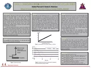
Load (N) 40 30 20 10 0 0 1 2 3 4 5 6 7 8 9 10 11 12 Spring Deformation (mm) Handle with weight Spring is located between handle and shaft Ski pole Drop height Force platform Biomechanics Laboratory SHOCK ABSORBING CROSS-COUNTRY SKI POLE FOR DRYLAND SKIING Andrew Post and D. Gordon E. Robertson School of Human Kinetics, University of Ottawa, Ontario, CANADA, K1N 6N5 Introduction Some research has gone into the forces that are produced during the pole plant phase of cross-country roller skiing (Street & Frederick, 1995; Komi, 1988; Millet et al., 1998a,b,c). Due to the hard surface (usually asphalt) into which the roller skiers plant their poles there are much higher forces travelling through the pole than with ordinary snow skiing. These high ground reaction forces have been identified as a possible cause of injuries to the wrists, elbows and shoulders of roller skiers To date few studies have tried to resolve this problem by inserting a shock absorbing mechanism into the ski pole. In the present experiment pole forces were examined before and after a shock absorbing mechanism (a spring) was inserted into a normal Nordic ski pole. The spring was inserted into the shaft of a carbon fibre cross-country ski pole between the handle and the shaft. Methods To simulate the load created by the arm, a 1.13 kg (2.5 lbs) mass was attached to the handle above the spring. The ski pole was dropped from a support that was set up over a force platform (Kistler). The pole was dropped five times for each of the four pole/height conditions: 20 and 40 cm with and without the spring. The pole wassuspended by a fish line and the drop height was measured by an anthropometer to ensure repeatable impulses. The force platform was covered with a steel plate to protect it from the carbide tips of the ski pole and to elevate the resonant frequency. The resonant frequency of the force platform was measured to be approximately 780 Hz. Results The peak vertical forces for the 20 cm trials were 480+/-60 N and 250+/-50 N for the standard versus the modified poles, respectively. The peak vertical forces for the 40 cm trials were 766+/-49 N and 615+/-64 N for the standard versus modified poles, respectively. Thus, the spring reduced the peak vertical force by 27% for the 20 cm drop height and 20% for the 40 cm drop height. Figure 3 shows mean vertical force histories (n=5) for the normal and modified poles for the 40 cm drop. Notice that the spring dissipates the impact forces by spreading the forces over a longer duration and creating negative vertical forces. The reduced peak forces are comparable to those reported by Wells (1988) for cross-country skiers on snow. Presumably, the spring has reduced the peak forces low enough to prevent stress related injuries. Summary To In summary, the trials to test the modified ski pole successfully simulated a standard pole plant on a harder than snow surface. The results showed that the forces were reduced by the shock absorbing system that was installed on the ski pole. While the modified pole was successful in a laboratory environment it is essential to estimate its durability and its functionality in a field setting for its use by the general public and athletes. Purpose To investigate the shock absorption of a ski pole with and without a spring inserted in the handle. Figure 2. Load-deformation curve of spring. Stiffness = 2.59 N/mm. References Komi P.V. (1988)Amer Ski Coach. Vol 11(5). Kannus P., Niittymaki S., Jarvinen M. (1988) Scand J of Sports Sci 10, 17-21. Millet G.Y., Hoffman M.D., Candau R.B., Clifford P.S. (1998a) Med & Sci Sports & Exer 30, 1637-1633. Millet G.Y., Hoffman M.D., Candau R.B., Clifford P.S. (1998a,b) Med & Sci Sports & Exer 30, 1645-1653. Millet G.Y., Hoffman M.D., Candau R.B., Buckwalter, J.B., Clifford P.S. (1998c) Med & Sci Sports & Exer 30, 755-762. Street M.G. & Frederick E.C. (1995) J Appl Biomech, 11, 245-256. Wells R. (1988) Proc. 5th Conference of Can Soc for Biomechanics. 166. Figure 3. Vertical forces from 20 cm drop test of a loaded ski pole with and without spring in handle Figure 1. Experimental setup.


