Download
1 / 84
890 likes | 1.02k Views
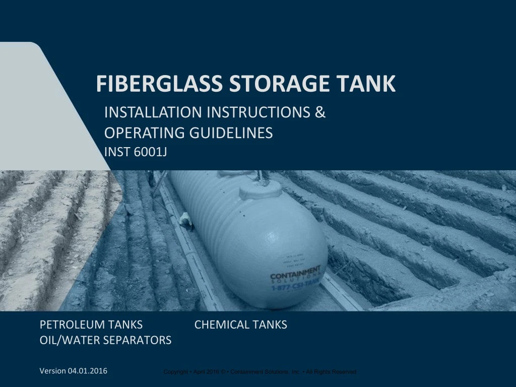
FIBERGLASS STORAGE TANK. Installation Instructions & Operating Guidelines INST 6001J. PETROLEUM TANKS CHEMICAL TANKS OIL/WATER SEPARATORS. Version 04.01.2016. Agenda. Introductions Review Key Installation Procedures (PPT) Written Exam Contractor Documentation

E N D
FIBERGLASS STORAGE TANK Installation Instructions & Operating Guidelines INST 6001J PETROLEUM TANKS CHEMICAL TANKS OIL/WATER SEPARATORS Version 04.01.2016
Agenda • Introductions • Review Key Installation Procedures (PPT) • Written Exam • Contractor Documentation • Submit Signed Attachment Eas a Record of Training • Review Missed Questions • 2-Year Renewal
Important Documentation • Remember to barricade tank area. • Complete installation checklist. • Review shipping packet contents.
Important Documentation The Installation Checklist: • Is included in the installation instructions. • MUST be filled out for each tank on every project. • MUST be retained by the tank owner and provided to CSI to validate any future warranty claim.
PRE installation preparation Sections 1 & 2
Safety Reminders(Section 1.6 Paraphrased) • Pay close attention to the important safety comments throughout the Installation Instructions. • Remember to follow all OSHA, EPA and local regulations which apply.
Handling/Storage(Section 2.1 paraphrased) Handling/Preparation: • All tanks must be mechanically unloaded. • Carefully unload all accessories to prevent damage. For temporary job site storage: • Use provided shipping pads or approved tank backfill. • Chock tanks with sandbags. • Place on smooth ground. • Tie down tank in anticipation of high winds. • Protect collars from freezing conditions.
Handling / Storage(Section 2.3 Paraphrased) Tanks • There are different tank orientations for unloading or lifting into the excavation. • Identify the tank lift lug orientation and use the appropriate method to lift the tank.
Handling / Storage(Section 2.4 Paraphrased) Unloading Deadmen: • Ensure lifting equipment is rated to handle the full load before lifting. • Use a minimum of 2 equally spaced anchor points(see Figure 2-4).
Bed & Backfill Section 3
Bed & Backfill(Section 3.3 Paraphrased) Approved Backfill • Always use approved pea gravel or crushed stone. • Require sieve analysis from your backfill supplier. • Do not use sand or native soil. • To check your backfill size and receive a job specific email acknowledgement, go to www.contamentsolutions.com.
Bed & Backfill(3.3.5 Paraphrased) • Clean and washed backfill material only. • Crushed Stone no larger than ½” (see Figure 3-1). • Rounded Pea Gravelno larger than ¾”(see Figure 3-1). • No more than 5% passing #8 sieve. Backfill calculator on CSI website to confirm sieve analysis
PRE-INSTALLATIONTESTING Section 4
Prepare For Testing(Section 4.3 Paraphrased) • Connect a “Tank TestManifold” to a primary fitting(see Figure 4-1). • Use pressure gauge of 15 psigor less (max ¼ psig increments). • Use pressure relief device toensure tank pressure does notexceed 5 psig (3 psig for 12’ tanks). • For any tank model with a dry interstitialspace (including a double-wall bulkhead) connectan “Annular Space Gauge and Valve” to anannular space fitting (see Figure 4-2). Annular Space Gauge and Valve (Contractor Supplied) Tank Test Manifold (Contractor Supplied)
Prepare For Testing(Section 4.6 Paraphrased) • Soap entire tank and inspect for air bubbles. • Soap all fittings and manways. • Contact CSI Field Service immediately in the unlikely event a leak is discovered.
Testing All Fiberglass Tanks Single-Wall Tank Test is in Section 5.1 Double-Wall Tank Tests are only in Sections 5.2 – 5.6. Non-Air Test Tank Test is found in Section 5.7 Determine which section is appropriate. Follow each step of the instructions provided in the Tank Installation Instructions.
Single-Wall Tank Testing Procedures – Section 5.1 Double-Wall Tank Testing ProceduresShipped Under Vacuum – Section 5.2 Testing Double-Wall Tank(s)with Dry Annular Space – Section 5.3 Testing Double-Wall Compartment Tank(s) with a Dry Annular Space & Double-Wall Bulkheads – Section 5.4 Testing Double-Wall Tank(s) with Liquid Filled Annular Space (Hydrostatically Monitored) – Section 5.5 Testing Double-Wall Compartment Tank(s) with Double-Wall Bulkheads (Hydrostatically Monitored) – Section 5.6 Tank Testing Procedures Section 5
Single-Wall Tank Testing Procedures Section 5.1
Testing Single-Wall Tanks(Section 5.1 Paraphrased) Pressurize tank to 5 psig maximum (3 psig for 12’ tanks)(see Figure 5-1). Close the air supply valve to the primary tank. Disconnect the air supply. Monitor the pressure readings for 30 minutes for any loss in pressure from the initial reading which may indicate a leak. While under pressure, cover tank outer surface including fittings and manways, with soap solution and inspect.
Double-Wall Tank Testing Procedures Shipped Under Vacuum Section 5.2
Testing Tanks Under Vacuum(Section 5.2 Paraphrased) • After backfilling to tank top • Pressurize only the primary tank and all compartments while maintaining vacuum on the annular space. Cover fittings and manway(s) with soap solution and inspect. • In the unlikely event a tank leak is discovered, discontinue the installation and immediately callCSI Field Services to schedule a repair. • A tank shipped under vacuum can be installed and backfilled with the vacuum intact if both of the following conditions are met: • The vacuum date precedes the tank installation by at least 7 days. • The vacuum gauge reads at least 10”Hg (34kPa).
Testing double-wall tank(s) with dry annular space Section 5.3
Testing Double-Wall Tanks with Dry Annular Space(Section 5.3 Paraphrased) • Maintain pressure on the annular space(see Figure 5-4). • Observe and monitor the gauge on the annular space for 30 minutes for any loss of pressure which may indicatea leak. • While under pressure, cover tank outer surface, includingfittings and manway(s), with soap solution and inspect. Pressurize tank to 5 psig maximum (3 psig for 12’ tanks)(see Figure 5-2). Open valve between primary tank and annular space in order to pressurize the annular space using the existing pressure in the primary tank (pressure in the primary tank may drop slightly)(see Figure 5-3). While under pressure, cover fittings and manway(s) with soap solution and inspect.
Testing Double-Wall Compartment Tank(s)With Dry annular Space and double –wall bulkhead(s) Section 5.4
Testing Double-Wall Compartment Tanksw/ Dry Annular Space & Double-Wall Bulkhead(Section 5.4 Paraphrased) • Monitor the pressure for 30 minutes for any loss in pressure from the initial reading which may indicate a leak. • With all compartments under pressure, cover fittings and manway(s) with soap solution and inspect. • Open valves to vent all compartments (maintain 5 psig on annular space)(see Figure 5-6). • Monitor the pressure for 30 minutes for any loss in pressure from the initial reading which may indicate a leak. • While under pressure, cover tank outer surface, including fittings and manway(s), with soap solution and inspect. • Connect the pressure source to the “Tank Test Manifold” on each compartment. • Pressurize all compartments to 5 psig (3 psig for 12’ tanks) (see Figure 5-5).
Testing Double-Wall Tank(s) with liquid filled annular space (Hydrostatically Monitored) Section 5.5
Testing Double-Wall Tanksw/ Hydrostatically Monitored Space(Section 5.5 Paraphrased) • Connect “Tank Test Manifold” to a primary tank fitting. • Connect the pressure source to the “Tank Test Manifold.” • With a light, look inside for any monitoring fluid. • Replace and tighten fitting plug(s). • If monitoring fluid is found on the tank inner or outer surface during any test, discontinue the installation and immediately contact Containment Solutions Field Services. Posed image for illustration purposes
Testing Double-Wall Tanksw/ Hydrostatically Monitored Space(Section 5.5 Paraphrased) Pressurize primary tank to 5 psig maximum (3 psig for 12' tanks) (see Figure 5-8). Close valve on “Tank Test Manifold.” Disconnect the air supply line. Monitor the pressure for 30 minutes for any loss in pressure from the initial reading which may indicate a leak. While under pressure, cover tank fittings and manway(s), with soap solution and inspect.
Testing Double-Wall Compartment Tank(s)double –wall bulkhead(s)(hydrostatically monitored) Section 5.6
Testing Double-Wall Compartment TanksDouble-Wall Bulkhead (Hydrostatically Monitored)(Section 5.6 Paraphrased) • Connect the pressure source to the “Tank Test Manifold” on each compartment. • Pressurize all compartments to 5 psig (3 psig for 12’ tanks) (see Figure 5-10). • Monitor the pressure for 30 minutes for any loss in pressure from the initial reading which may indicate a leak. • While under pressure, cover tank outer surface, including fittings and manway(s), with soap solution and inspect.
Excavation Section 6
Excavation(Section 6 Paraphrased) • Stable Soil(see Figure/Table 6-1) • Minimum spacing between tanks and excavation walls, in stable soils. • Example: with no mechanical anchoring, a 10’ diameter tank will need a minimum 18” spacing between tanks and 24” spacing between the tank and the excavation walls. • Unstable Soil(see Figure/Table 6-2) • Minimum spacing between tanks and excavation walls, in unstable soils. • In unstable excavations the spacing between the excavation walls and the tank should always be a minimum of ½ the diameter of the tank. Sizing • Minimum spacing between tanks is 18” when no mechanical anchoringis required. • Tank spacing depends on soil in the excavation as well as the choice of anchoring systems. • When job site conditions require an oversized hole, fill the entire excavation with approved backfill.
Geotextile Fabric(FILTER FABRIC) Section 7
Geotextile Fabric(Section 7 Paraphrased) Usage Geotextile fabric is required between backfill and nativesoils for certain installations such as unstable soils, swampy areas and landfills to prevent backfill from migrating and thereby undermining support of the tank, piping or paving. Do not use plastic, or any other material that may tear or degrade, as a replacement for geotextile fabric.
Burial Depth & Cover Section 8
Burial Depth and Cover(Section 8 Paraphrased) • No Traffic Loads: • 4’-10’ tanks need a minimum of 24” backfill or 12” backfill and 4” reinforced concrete (see Figure 8-2). • 12’ tanks need a minimum 42” backfill or 38” backfill and 4” reinforced concrete. • For Traffic Loads: • 4’-10’ tanks need a minimum of 36” backfill or 18” backfill and 6” reinforced concrete (see Figure 8-3). • 12’ tanks need a minimum 48” backfill or 36” backfill and 6” reinforced concrete. • Minimum burial depth may not be sufficient to anchor the tank in buoyant conditions (see Figure 8-1). • Traffic pad must extend at least 12” beyond tank perimeter in all directions. • The maximum burial depth is 7’ from the tank top to grade elevation. • Dry hole excavations must have a minimum of 12” and a maximum of 24” backfill between the bottom of the tank and either the bottom of the excavation or the top of the concrete anchor pad.
Tank Anchoring Section 9
Tank Anchoring(Section 9 Paraphrased) For minimum burial depths refer to the Anchoring Chart in Installation Instructions INST 6001 (Appendix A) • If water can enter the tank excavation, CSI recommends mechanical anchoring. • Use only CSI fiberglass anchor straps. • Deadmen or concrete anchor pads may be used. • After installation, all exposed metal should be coated or galvanizedto protect against corrosion. • The mechanical anchoring methods are shown in Figure 9-1. Anchor Straps • Use correct length anchor straps for each diameter tank (see Figure 9-2). • Anchor points must be aligned with designated anchor ribs ►◄ (±1"). Do not use straps between ribs except on 4' tanks. • Use one anchor point per strap end. Anchor Point Loads: • For any anchoring system, the tank strap and all hardware should be designed for the following working loads which will provide a minimum 3:1 factor of safety (see Table 9-1). • Must have anchor points at the bottom of the hole aligned within 1” of the designated rib. • Should be tightened to give a snug fit. • Are available in a convenient man-out-of-hole split strap option. The three common methods are: • Deadmen Anchors. • Concrete Anchor Pad. • Overburden (no mechanical anchoring).
Tank Anchoring(Section 9 Paraphrased) Anchor Pad: • As a minimum the anchor pad for stable excavations must be at least 8" thick, with #6 rebar on 12" centers each way. • When a concrete anchor pad is used the tank and pad must be separated by at least 12” of approved pea gravel or crushed stone backfill. • Embedded anchor points must be designed for the working loads in Table 9-1. • When embedding anchor points at the time the pad is fabricated, the following design will meet the minimum required anchor points(see Figure 9-6). Standard installation is bottom of deadman even with bottom of tank Section H • Lay the deadmen in the excavation parallel to the tank and outside of the tank shadow(see Figure 9-5). • Each tank requires its own deadman on both sides, or if one deadman is used between adjacent tanks, it must be doubled in width. • Place multiple deadmen, in contact, end to end.
Ballasting Tanks (Adding Liquid) Section 10
Wet Hole- Add enough ballast to sink the tank. Ballast level inside the tank and in all compartments should be equal (to keep tank level) and not more than 12” above the ground water level outside the tank (see Figure 10-1). • Use water or fluid heavier than water as ballast. Be sure the ballast will not contaminate the product being stored or clean the tank before product is added. • Do not make a direct (hard) connection of the ballast fill line to any tank fitting. • At the moment the tank is full, the pressure in the fill line will result in an instant pressurization of the tank which will damage the tank. • This problem can be avoided by providing adequate tank venting or removing the fill line and manually bringing the tank to full capacity. • Dry Hole- add ballast only after backfill is placed at least 75% of the tank diameter. Ballasting Tanks(Section 10 Paraphrased)
Vertical Diameter Measurements Section 11.2
Vertical Diameter Measurements(Section 11 Paraphrased) • Take the Fifth Vertical Diameter Measurement and record the value on the Tank Installation Checklist (see Figure 11-8). • The inner diameter measurement is calculated by subtracting the “Fourth Vertical Diameter Measurement” and “Fifth Vertical Diameter Measurement”. • Backfill to tank top. • Take the Third Vertical Diameter Measurement and record the value on the Tank Installation Checklist and verify measurement“A” does not exceed the value in Table 11-1 in INST 6001 on page 19 (see Figure 11-6). • If mechanical anchoring is used, after anchoring is completed, take the “Second Vertical Diameter Measurement” and record the value on the Tank Installation Checklist. If this value does not equal the “First Vertical Diameter Measurement”, loosen the anchor straps (see Figure 11-2). • Set tanks directly on backfill bed. • Take the “First Vertical Diameter Measurement” and record the value on the Tank Installation Checklist (see Figure 11-1). • Once the tank has been backfilled to subgrade, before placement of concrete pad, take the fourth vertical diameter measurement (see Figure 11-7). • Record the value on the Tank Installation Checklist. Section I • Excessive Deflection (loss of vertical diameter) of any installed tank can create stress on the tank. • The major cause of deflection is the loss of tank support because of improper backfill material or installation method. • Compare all deflection measurements to the limits established by CSI on the Tank Installation Checklist. • There are 5 total vertical diameter measurements.
Tank Installation Procedures Section 11
Installation Procedure – Dry Hole(Section 11.3 Paraphrased) • Proper backfilling is required to provide necessary support for the tank. • Place the first 12” lift of approved backfill material evenly around the tank. Push the backfill in place by using a probe long enough to reach beneath the tank, eliminating all voids, so the tank is fully supported (see Figure11-3). • Eliminate all voids by using a long handled probe to push backfill: • Completely beneath tank bottom. • Completely between the 5 o’clock and 7 o’clock positions along the entire length of the tank (see Figure 11-4). • Repeat this process with a second 12” lift, eliminating all voids. Ballast tank only AFTER backfill is to 75% of tank diameter
INSTALLATION PROCEDURES – WET HOLE • Water level in the excavation should be maintained at lowest practical level by using pumps. • Ballast the tank if ground water cannot be lowered(refer Section 10).
Piping &bottom sump clearances • Section 13