Download
1 / 26
260 likes | 428 Views
FPGA-BASED HARDWARE EMULATION OF IMAGE MORPHING FINAL PRESENTATION CprE 583, Fall 2011. Project T eam. Talha Ansari, Technical Approach/VHDL implementation Heather Garnell, Technical Approach/VHDL implementation Anamika Shams, Testing Requirements/Implementation. Motivation.

E N D
FPGA-BASED HARDWARE EMULATION OF IMAGE MORPHING FINAL PRESENTATIONCprE 583, Fall 2011
Project Team Talha Ansari, Technical Approach/VHDL implementation Heather Garnell, Technical Approach/VHDL implementation Anamika Shams, Testing Requirements/Implementation
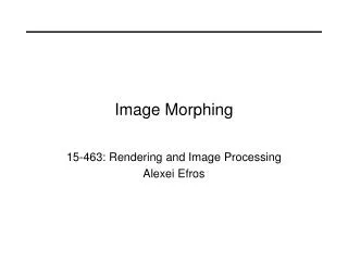
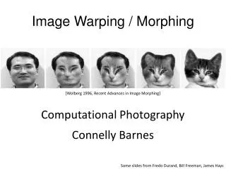
Motivation Image morphing is a useful and widely recognized visualization technique. Thus there is interest in and research conducted in this area. Image morphing techniques can generate compelling 2-D transitions between images and thus will add an element to fun to the entire project development process.
Scope & Objective To implement image morphing on the ML507 test board using both the xilinx FPGA and the PPC 440 • From Iowa State CprE583 Fall 2011 lecture 12
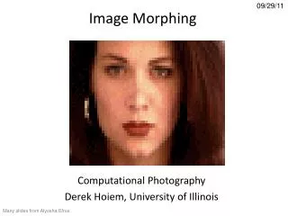
End Product Of Morphing The final product will include two similar images and a final morphed image similar to the images you see below.
High-Level Algorithms The concept of Barycentric Coordinates can be used in an image morphing application http://www.cs.washington.edu/homes/ankit/course_projects/files/DIP/A2_web/marked6.jpg
read find_bary_coordinate compute_ABCts main bary compute_gamma write compute_alpha get_tri_area compute_beta Flow of C Code
Flow of C Code (Contd..) Compute_ABCts: This function compute time interpolation of ABC_0 and ABC_1 for AtBtCt triangle by looping through 8 triangle, 3 points of each triangle and the 2 coordinate of the each triangle Get_Tri_Area: This method is getting the area of the corresponding point P1, P2 and P3 of the new triangle. Compute_Alpha: This function compute the new triangle area in regards to ABC triangle and PBC triangle Compute_Beta: This function compute the new triangle area in regards to ABC triangle and PAC triangle Compute_Gamma: This function compute the new triangle area in regards to ABC triangle and PAB triangle. Find_Bary_Coordinate: This function find two coordinate points x and y from the ABC triangle area. Bary: This method is computing the morphed triangle at time t where due to the affine invariant property, the corresponding point Po in triangle AoBoCo and PI in triangle A,BICI are Po = atAo + BtBo + YtCO and PI = atA I + BtBI + YtC" respectively. If the colors of Po and PI are I0 and I1, respectively, the color at Pt will be computed same as simply using this function It = (l-t)Io + tIl. Therefore, every pixel of triangle AtBtCt is interpolated from its initial color in triangle AoBoCo and its final color in triangle AIBICI. Read: This method open the bmp file and read the header and the color of two images files and then close the file. Write: This function open the final morphed image file and write the morphed image.
Hardware Design Goals To reuse MP3 architecture as much as possible Offload PPC with pixel morphing Load 120 bits (5 pixels) from each picture in two consecutive loads Take average of each pixel element Send modified data back to PPC
Design Integration Step 1: Design C code on local computer and test out Step 2: Design VHDL merging function and test out Step 3: Integrate C code on PPC Step 4: Integrate VHDL code by offloading pixel merging to FPGA Step 5: Test system out
Step 1 Complete C code implementation alpha = compute_alpha(ABC_t, uv); beta = compute_beta (ABC_t, uv); gamma = compute_gamma(ABC_t, uv); // Let Pt be a point of triangle AtBtCt. // Its barycentric coordinate with respect to triangle AtBtCt, can be found as // Pt = ætAt + ßtBt + YtCt where æt/=0, ßt/=0, Yt/=0, æt+ßt+Yt=1 Pt = find_bary_coordinate(alpha, beta, gamma, ABC_t); // From the coordinate (æt, ßt, Yt) of point Pt, due to the affine // invariant property, the corresponding point // P0 in triangle AøBøCø = ætAø + ßtBø + YtCø // P1 in triangle A1B1C1 = ætA1 + ßtB1 + YtC1 P0 = find_bary_coordinate(alpha, beta, gamma, ABC_0); P1 = find_bary_coordinate(alpha, beta, gamma, ABC_1); // If the colors of P0 and P1 are I0 and I1, respectively, // the color at Pt is simply: It = (1-t)I0 + tI1 // Compute It for red, green, and blue pixels temp_red = (1.0-t)*(float)(I0.red) + t*(float)(I1.red); // Red temp_grn = (1.0-t)*(float)(I0.grn) + t*(float)(I1.grn); // Green temp_blu = (1.0-t)*(float)(I0.blu) + t*(float)(I1.blu); // Blue SINGLE_PIXEL It = { (int)(temp_red), (int)(temp_grn), (int)(temp_blu) };
Images before processing with Morphing application It is important for images to be the same size and orientation. Source images were chosen because they met this criteria.
Step 1 (Cont.) Each of the two input images broken into eight triangles
Final morphed image based on the previous slide’s two images
Step 2 VHDL implementation complete
Step 3 Currently at this step of integration Minor issues with integration of current c code into out echo.c
Step 4 Next step
Step 5 This is where magic happens!!!
Related Papers Ching-Kuang Shene. "Barycentric Coordinates and Morphing,” Department of Computer Science. Michigan Technological University. April 19, 2003. - This is a practical guide for implementing barycentric coordinates into an image morphing application. T. Balercia, A. Zitti, H. Francesconi, S. Orcioni and M. Conti. "FPGA Implementations of a Simplified Retinex Image Processing Algorithm." IEEE 2006.
Current Status Resolve issue with final morphing of pixel data within c code as this the morphing algorithm itself was not the purpose of the project, we chose to resolve this between now and final submission Complete integration effort Modify documentation based on any recent changes to project design or implementation Complete writing the final report
Lessons Learned Set times when the entire group can meet to discuss topics proved to be difficult with work schedules and family issues. Use of chat programs was very helpful to keep communication lines open Use of tools to keep documentation in a common location was helpful (Google docs and Google sites) Check for integration issues early on is important
Questions or Comments? Thank you!