Download

1 / 64
660 likes | 967 Views
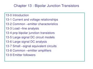
Chapter 13 Bipolar Junction Transistors. Chapter 13 Bipolar Junction Transistors. 1 . Understand bipolar junction transistor operation in amplifier circuits. 2 . Analyze simple amplifiers using the load-line technique and understand the causes of nonlinear distortion.

E N D
Chapter 13Bipolar Junction Transistors 1. Understand bipolar junction transistor operation in amplifier circuits. 2. Analyze simple amplifiers using the load-line technique and understand the causes of nonlinear distortion.
3. Use large-signal equivalent circuits to analyze BJT circuits. 4. Analyze bias circuits. 5. Use small-signal equivalent circuits to analyze BJT amplifiers. 6. Compute performance of several important amplifier configurations. 7. Select an amplifier configuration appropriate for a given application.
LOAD-LINE ANALYSIS OF A COMMON-EMITTERAMPLIFIER(Input Circuit)
LOAD-LINE ANALYSIS OF A COMMON-EMITTERAMPLIFIER(Output Circuit)
When iCbecomes zero, we say that the transistor is cutoff. When vCE0.2 V, we say that the transistor is in saturation.
PNP BIPOLAR JUNCTION TRANSISTORS Except for reversal of current directions and voltage polarities, the pnp BJT is almost identical to the npn BJT.
ib(t) denotes the signal current flowing into the base, IBQis the dc current that flows when the signal is absent, and iB(t) is the total base current. Similar notation is used for the other currents and voltages.