Download
1 / 35
360 likes | 525 Views
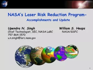
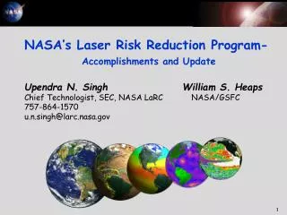
NASA’s Laser Risk Reduction Program- Accomplishments and Update Upendra N. Singh William S. Heaps Chief Technologist, SEC, NASA LaRC NASA/GSFC 757 -864-1570 u.n.singh@larc.nasa.gov. Outline. Background LRRP Strategy and Synergies Objectives and deliverables

E N D
NASA’s Laser Risk Reduction Program-Accomplishments and UpdateUpendra N. SinghWilliam S. Heaps Chief Technologist, SEC, NASA LaRC NASA/GSFC 757-864-1570u.n.singh@larc.nasa.gov
Outline • Background • LRRP Strategy and Synergies • Objectives and deliverables • Recent Accomplishments • Future Plans • Conclusions
Laser Risk Reduction Program Origins • Earth Science Independent Laser Review Board empanelled in 2000 in response to multiple laser instrument mission issues • Panel reviewed past and present NASA ESE laser remote sensing missions: • CALIPSO, ICESat, LITE, SPARCLE (NMP/EO-2), VCL • Panel report included 11 recommendations, the most key being: • NASA should identify and intensively develop critical fundamental technologies applicable to multiple missions and investigate formation of interagency coalition to assure supply of diode pumped lasers • NASA should create a “Laser Research Super Center” managed by NASA HQ and drawing from laser research teams at the field centers • An interagency technology alliance should be formed for the development of space-based active optical sensors and associated critical enabling technologies (especially transmitter-class lasers) • NASA Administrator mandated formulation of an Agency-level lidar technology development plan • Laser Risk Reduction Program (LRRP) was established, based on recommendations from joint LaRC/GSFC strategy team • Program initiated in FY02 • Co-funded by ESTO and Code R Enabling Concepts and Technologies (ECT) program
INLSST Charter • Develop lidar technology for NASA’s future measurements • Assemble in-house NASA team with end-to-end lidar capability (theory to hardware to validation) • Collaborate with industry, academia, and government • Validate technology to reduce risk of space-based lidar missions before the proposal process • Transfer technology to industry
Overview Laser based instruments are applicable to a wide range of Earth Science, Aerospace Technology, Space Science, and Space FlightEnterprise needs Risk in lidar missions can be significantly reduced by progress in a few key technologies Modest NASA investment towards proposed strategy will have significant impact on future space-based active remote sensing missions Strategic alliance with other government organizations, industry, and academia for leveraging and accelerating advancement of key technologies
Integrated NASA Lidar Systems Strategy Team Report Presentation to Daniel S. Goldin,NASA Administrator By Ghassem R. AsrarSamuel L. Venneri Associate Administrator Associate Administrator Earth Science Enterprise Aerospace Technology Enterprise Jeremiah F. CreedonAlphonso V. Diaz Director, NASA LaRC Director, NASA GSFC Upendra N. Singh and William S. Heaps Co-Leaders Integrated NASA Lidar Systems Strategy Team (INLSST) June 18, 2001 Draft Copy Preliminary Draft – For Agency Use Only
Turbulence detection Wind shear detection Wake vortices Automatic Rendezvous and Docking for ISS Wind profiling for shuttle launch and landing Lidar is a Multi-Enterprise Need • Clouds/Aerosols • Tropospheric Winds • Ozone • Carbon Dioxide • Biomass Burning • Water Vapor • Surface Mapping • Laser Altimetry • Oceanography NASA Enterprises Needs Earth Science Aerospace Technology Laser Technology Space Flight Space Science Mars Lander Guidance/Control Mars Atmospheric Sensing
Earth Sciences Application Foci Key Priority Measurements for Earth Science Enterprise • Cloud/Aerosols and Radiative Forcing • Tropospheric Winds/River Flow • Tropospheric Ozone • Carbon Cycle (CO2, Biomass) • Surface Mapping • Oceanography
Transmit Pulses Concentration = log[ I(lon)/ I(loff)] Returns Velocity = (l/2) fDoppler loff lon Wavelength Transmit Pulse Return Frequency fDoppler Density = IS/IT Range = (c/2)Tarrival IT Range = (c/2)TArrival Transmit Pulse Transmit Pulse Return Return IS Time Time TArrival TArrival Lidar Techniques and Measurements • Differential Absorption Lidar (DIAL) • Ozone • Carbon Dioxide • Doppler Lidar • Wind Fields • River Flow • Backscatter Lidar • Cloud • Aerosol • Altimetry Lidar • Ice Sheet Mass Balance • Vegetation Canopy • Land Topography
Earth Sciences Application Foci 2 Lasers,4 Techniques, 6 Priority Measurements Pulsed Laser Development 2.05 micron DIAL:CO2 Backscatter Lidar:Aerosols/Clouds Coherent Ocean/River Surface Currents 2 MICRON 2.05 micron Atmosphere: Lower Upper Doppler Lidar:Wind Key Technologies in Common Laser Diodes Laser Induced Damage Frequency Control Electrical Efficiency Heat Removal Ruggedness Lifetime Contamination Tolerance Coherent Winds Coherent Direct Noncoherent Winds 0.355 micron X3 1 MICRON X2 Altimetry: 1.06 micron Surface Mapping, Oceanography DIAL:Ozone X2 0.30-0.32 micron Backscatter Lidar: Aerosols/Clouds 0.532 micron OPO
Laser Transmitter Testbeds Contamination Tolerance Now: 50, A/10 Goal: Better Tolerance Laser Induced Damage Now: 15 J/cm2 for 5 nsec Goal: 60 J/cm2 for 5 nsec Ruggedness Now: 1 min @ 10G Goal: 1 min @ 15 G Lifetime Now: 850? M shots Goal: 2 G shots 2 µ Test Bed Knowledge 1 µ Test Bed Heat Removal Now: 110 Watts Goal: 300 Watts Frequency Control Now: < .25 pm Goal: < .005 pm Electrical Efficiency Now: 3-4% Goal: 6% 11
Recommendations • Establishing Space-hardened Laser Transmitter Test Beds (1µm laser at GSFC & 2µm at LaRC) • Development and Qualifications of Space-based Laser Diode Arrays ( 808nm diodes at GSFC & 792nm at LaRC) • Advancing Wavelength Conversion Technology for Space-based Lidars ( Low Energy/HRT at GSFC & High Energy/LRT at LaRC)
NASA Laser Risk Reduction Program • Deliverables • Space-hardened 1- and 2-micron Laser Transmitters (Efficient, Conductively-cooled) • Space-hardened Conductively Cooled Laser Diode Arrays • Non-linear Optical Parametric and Harmonic Generation for Ozone, Chemical and Biological Species, and Water Vapor Detection
Laser Risk Reduction Management Model OAT Code R OES Code Y GSFC Co-PI (W. Heaps) LaRC Co-PI (U. Singh) Project Manager (Cazeau) Project Manager (Kavaya) GSFC LaRC NASA HQ
LRRP Description • Pro-actively targets deficiencies in laser technology for focused development and risk mitigation • Technology readiness overestimated in past due to extrapolation from prior heritage • Flight lasers are still at the “build-to-order” R&D stage • Primary focus is on high-power (i.e., transmitter-class) lasers for space-based remote sensing applications • High-performance Nd:YAG systems (1 µm) • Emerging holmium- and thulium-doped lasant materials (2 µm) • Nonlinear generation schemes based on 1- and 2- µ m pump sources • Harmonic generation • Optical parametric amplification/oscillation (OPA/OPO) • Small investments in ancillary enhancing and enabling technologies which offer potential to reduce demand for laser power (detectors, innovative receiver approaches)
LRRP Application Driven Elements • 2-micron laser transmitter • Demonstrate technologies leading to a conductively cooled, diode-pumped 2-micron laser suitable for space-based lidar application • Address major laser development issues: High energy, high efficiency, laser-induced optical and thermal damage, system thermal management • High-power diode laser pump arrays • Develop, scale, and qualify long-lived, space-compatible laser diode arrays with current vendors • Evaluate currently available laser diode arrays for performance, life and configuration required for future space-based laser missions • Establish Characterization and Lifetime Test Facility to address laser diode issues: • Limited reliability and lifetime • Lack of statistical and analytical bases for performance and lifetime prediction • Conceive advanced laser diode array architectures with improved efficiency and thermal characteristics • Nonlinear optics research for space-based ozone DIAL • Spectrally narrow, tunable, robust UV laser architectures • Develop long-lived, efficient, space-compatible, nonlinear optical materials/techniques • Receiver technologies • Develop integrated heterodyne receiver to demonstrate 3-dB improvement of coherent lidar system efficiency with 80% reduction of required local oscillator power • Develop improved quantum efficiency photon-counting detectors at 2 micron • Laser physics and advanced materials research • Develop line tunable diode-pumped Nd laser system for pumping nonlinear UV generation schemes • Develop narrowband, long pulse, low average power pump laser for wavelength control of lidar systems
NASA Laser Risk Reduction Program • Differential Absorption Lidar (DIAL) • Carbon Dioxide • Ozone Laser Design Pump Diodes Wavelength Conversion Space Qualification • Doppler Lidar • Wind Fields • River Flow Heat Removal (All Conductive) Laser Physics OPO/OPA Performance Contamination Materials SHG/THG Compact Packaging Heritage derived from both Earth and Solar System apps. Modeling Optics Damage (2G/3 yr) • Backscatter Lidar • Cloud • Aerosol Efficiency (Green=30% UV=20%) Coupling Energy (1 J)/ Power (10-100W) Lifetime (2G Shots) Failure Mechanisms Efficiency (4% WPE) Beam Quality Lifetime Effects Beam Quality/ Spectrum Availability (COTS) • Laser Altimeter • Ice Sheet Mass and Topography • Vegetation Canopy • Land Topography • Ocean Mixed Layer Depth • S/C-S/C Ranging Flight Demonstrations 2-Micron Laser 1-Micron Laser 2003 2007 Missions
Scanner Receiver AutoAlign Pointing Telescope Detector Ranging/Altimetry X X Ozone Profiling X 2-Micron Lidar Transmitter X Water Vapor Profiling X Landing/Rendezvous Enabling Technology Elements Customers Laser Transmitter Technologies Lidar Technologies Measurements Y S UV Wavelength Converter 1-Micron Lidar Transmitter Clouds/Aerosols X X IR Wavelength Converter X Global Winds X X Amplifier X X Chem/Bio Sensing Frequency Controller CO2 Profiling X
Laser Risk Reduction Program • Pump Laser Diodes Risk Reduction • LaRC to advance diodes in 790 nm wavelength region • Lifetime and characterization testing • Radiation testing performed at GSFC • Conductively cooled laser • 2-micron partially conductively-cooled laser is precursor to fully conductively-cooled space-capable design • Contamination • GSFC Contamination protocols will be made available to support the contamination & lifetime study and tests at LaRC • Non-Linear Material & OPO Modeling • LaRC to develop high peak power OPO’s • Non-linear materials to be included in diode radiation test • Design and Packaging • Packaging methodology for space flight-capable laser A B C D E
Laser Risk Reduction ProgramLaRC Component FY 02 FY 03 FY 04 FY 05 FY 06 FY 07 C Contamination & Lifetime Study and Tests Material Res & Quantum Mech. Modeling Rad & Damage Tests Laser Resonator Power Efficiency Multi-Joule 12Hz 2-micron Transmitter Laser E Packaging (Flight-Hardened System) Global Winds & CO2 B Conductively-Cooled Laser Head Laser Amplifier Laser Oscillator ARad Th/Vac Tests Test/Charact. Facility Life Test Quality Test Perf./Reliability Laser Diodes Availability Life/Quality A Advance Laser Diode Technologies A Contamination & Handling Protocols Define Reqmts & Innovations Qualification Procedures Characterization Facilities Low-Noise Detector for CO2 Meas. Receiver Subsystem Efficiency Size/Mass Lightweight Scanning Telescope Global Ozone Highly-Efficient Heterodyne Receiver Define Reqmts & Innovations D Non-linear material & OPO modeling Dual Pump Parametric Oscillator Wavelength Conversion Power Efficiency 100mJ @ 100Hz 308nm & 320nm 2% efficiency Efficient conversion to UV Damage/Rad/ Life Tests Packaging Lab Demo High Power Conversion to UV Normal Mode Intra-cavity SHG Pump Laser
Laser Risk Reduction Program2-micron technology roadmap FY 02 FY 03 FY 04 FY 05 FY 06 FY 07 Partially conductively-cooled osc 1.5J, 2Hz Partially conductively-cooled 2-micron laser Laser Resonator Design Partially conductively-cooled laser head Validation tool Partially conductively-cooled amp Design Lessons Design Lessons Design Lessons Fully conductively-cooled osc 1.5J, 10Hz Fully conductively-cooled 2-micron laser Space-capable design Fully conductively-cooled laser head Fully conductively-cooled amp
2-Micron Pulsed Transmitter Laser Objective: Develop a high energy, high efficiency, conductively-cooled solid-state 2-micron laser for space lidar applications. Application: Measurement of global CO2 and winds from LEO. 1 J • Accomplishments • Successful demonstration of Ho,Tm:LuLF laser system with 1050 mJ Q-switched output energy. This was accomplished by one power oscillator and two amplifiers operating in double pulse mode. Single-pulse output is 0.6 J. • Notional space-based wind profiling missions require pulse energies from 1 to 5 J, depending on the scenario • Milestone achieved with 2-Hz PRF; >12 Hz desired for LEO
Pump Laser Diode Advancement and Validation Objective • Develop state-of-the-art characterization and life-time test facility and address 792-nm laser diode issues: • Limited reliability and lifetime • Lack of statistical and analytical bases for performance and lifetime prediction • Limited commercial availability • Develop advanced laser diode array (LDA) architectures with improved efficiency and thermal characteristics Thermal Image of Diamond LDA Accomplishments Fabricated and tested an advanced LDA package utilizing diamond substrate and heatsink. Demonstrated 17% reduction in thermal resistance relative to the standard BeO/Cu package that can translate to increased lifetime and reliability. Diamond Package cools 36% faster
LRRP Recent Accomplishments • Reached 150 mJ (record) of UV at 320 nm with 10% (record) 1µm-UV efficiency; reached 115 mJ at 308 nm • Developed innovative UV generation architectures • Critical to trop ozone profile measurement from space
Laser Risk Reduction Program- Collaborations • Current partnerships and collaborations • JPL • Tunable LO Laser • Integrated Receiver • VLOC, CVI • Optics • Coatings • Coherent, CEO, • Laser Diodes • Northrop Gruman • Solid State Lasers LaRC GSFC NASA Laser/Lidar Risk Reduction Program • Swales, UMD • Cond. Cool. Pkg. • DOE • UV Laser • ITT • UV Laser • JHU, APL • Non Linear Op • Schafer, • Plasma Processes • Lightweight Telescopes • Sci. Material • Laser Crystals • Boston College • Quan. Mech. Model. • DOD • Laser Diodes, • EO Scanner • Industry • University • Government
Proposal for a Multi-Agency AORS Consortium • National Consortium for Excellence in Active Optical Remote Sensing (AORS) • Purpose: To establish and maintain critical national expertise needed to ensure long term progress in AORS; mount compelling case for new USG initiative in FY05-06 timeframe • Participants: • A multi-agency entity (e.g., NASA, NOAA, IPO, DoD, DoE, FAA, Homeland) • Engages members of academia and industry • Approach: • Leverages complementary activities ongoing in each of those organizations • Primary interchange through open discussions
Proposed Consortium Partners and Measurement Needs Clouds/Aerosols Wind Trop. Chemistry Carbon dioxide Biomass Water Vapor Land/Ice Topography Wake Vortices Ocean Mixed Layer Solar System Science NSF Chem-Bio Detection Aviation Safety Wake Vortices Turbulence Wind Shear Academia Industry NASA FAA Chem-Bio Det Aerosols Wind Aviation Safety Multi-Agency Active Optical Remote Sensing Consortium Wind Water Vapor CO2 Aerosols Home- land NOAA Wind Humidity Aerosols Wind Aerosols Chem-Bio Detection Target Recognition Tactical Imaging IPO DoD DoE Water Vapor Chem- Bio Detection Clouds and Aerosols
Consortium Structure Wind • NOAA • NASA • IPO • DOD • Homeland Chem-Bio • NASA • DoE • DOD • Homeland • FAA CO2/O3 • NOAA • NASA • EPA • NSF Executive Council Steering Committee Working Groups Ranging Clouds/ Aerosols Aviation Safety • NASA • USGS • DOD • Homeland • NOAA • NASA • IPO • DOD • Homeland • NASA • FAA • DOD • Homeland Water Vapor Wake Vortices • NOAA • NASA • IPO • DOE • EPA • FAA • NASA • DOD
Advanced AORS Technology Elements AORS System Demonstration Packaging & Hardening Flight Validation DETECTOR TELESCOPE SCANNER RECEIVER Auto-Alignment POINTING
Summary • Developing AORS technology supports NASA’s Vision and Mission and enables a key “building block” • A focused technology effort will enable the promise of AORS by closing critical remaining gaps in capability • AORS will address key high resolution measurement needs within Codes Y and S and support other national needs
Contamination & Lifetime Study and Tests Material Res & Quantum Mech. Modeling Rad & Damage Tests Laser Resonator Power Efficiency Multi-Joule 12 Hz 2-Micron Transmitter Laser Global Winds & CO2 Laser Oscillator Packaging (Flight-Hardened System) Laser Amplifier Conductively-Cooled Laser Head Test/Charact. Facility Life Test Quality Test Perf./Reliability Rad Th/Vac Tests Laser Diodes Availability Life/Quality Advance Laser Diode Technologies Contamination & Handling Protocols Define Reqmts. & Innovations Qualification Procedures Characterization Facilities Low-Noise Detector for CO2 Meas. Receiver Subsystem Efficiency Size/Mass Lightweight Scanning Telescope Global Ozone Meas. Highly-Efficient Heterodyne Receiver Define Reqmts & Innovations Non-linear Material Res. & OPO Modeling Dual Pump Parametric Oscillator Wavelength Conversion Power Efficiency 500 mJ X 10 Hz 308nm &320 nm 2% Efficiency Efficient, High E Conver to UV Damage/Rad/ Life Tests Packaging Normal Mode Intra-cavity SHG Pump Laser Lab Demo High Power Conversion to UV Technology Roadmap: 2-micron & UV Sources
LRRP Recent Accomplishments • Developed diode laser characterization facility • Diagnostics to understand failure modes of solid state lasers • Enables active wind & CO2 measurement from space
LRRP Recent Accomplishments 792 nm Diamond Package LDA Diamond Package dissipates excess heat more efficiently than standard BeO/Cu package resulting in increased lifetime. Thermal resistance of diamond package is 17% lower than BeO/Cu package Pulsewidth 0.1 – 1.0 msec Current 80 A Rep Rate 10 Hz Op Temp 15oC
Thermal Characteristics of Diamond LDA • Enables all lidar measurements Diamond Package cools 36% faster