Download
1 / 43
430 likes | 644 Views
WELCOME. PRESENTATION ON OFFSHORE PLATFORM DESIGN WINNIE ANCHAN OMAR HAZZOURI. Welcome aboard exciting world of Offshore platforms design. In Next 45 minutes we will take you to educational trip of offshore platforms with breathtaking views and path breaking engineering accomplishments.

E N D
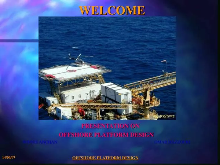
WELCOME PRESENTATION ON OFFSHORE PLATFORM DESIGN WINNIE ANCHAN OMAR HAZZOURI OFFSHORE PLATFORM DESIGN
Welcome aboard exciting world of Offshore platforms design. In Next 45 minutes we will take you to educational trip of offshore platforms with breathtaking views and path breaking engineering accomplishments. OFFSHORE PLATFORM DESIGN
OVERVIEW • Offshore platforms are used for exploration of Oil and Gas from under Seabed and processing. • The First Offshore platform was installed in 1947 off the coast of Louisiana in 6M depth of water. • Today there are over 7,000 Offshore platforms around the world in water depths up to 1,850M OFFSHORE PLATFORM DESIGN
OVERVIEW • Platform size depends on facilities to be installed on top side eg. Oil rig, living quarters, Helipad etc. • Classification of water depths: • < 350 M- Shallow water • < 1500 M - Deep water • > 1500 M- Ultra deep water • US Mineral Management Service (MMS) classifies water depths greater than 1,300 ft as deepwater, and greater than 5,000 ft as ultra-deepwater. OFFSHORE PLATFORM DESIGN
OVERVIEWOffshore platforms can broadly categorized in two types • Fixed structures that extend to the Seabed. • Steel Jacket • Concrete gravity Structure • Compliant Tower OFFSHORE PLATFORM DESIGN
OVERVIEW Structures that float near the water surface- Recent development • Tension Leg platforms • Semi Submersible • Spar • Ship shaped vessel (FPSO) OFFSHORE PLATFORM DESIGN
TYPE OF PLATFORMS (FIXED) • JACKETED PLATFORM • Space framed structure with tubular members supported on piled foundations. • Used for moderate water depths up to 400 M. • Jackets provides protective layer around the pipes. • Typical offshore structure will have a deck structure containing a Main Deck, a Cellar Deck, and a Helideck. • The deck structure is supported by deck legs connected to the top of the piles. The piles extend from above the Mean Low Water through the seabed and into the soil. OFFSHORE PLATFORM DESIGN
TYPE OF PLATFORMS (FIXED) • JACKETED PLATFORM (Cont.) • Underwater, the piles are contained inside the legs of a “jacket” structure which serves as bracing for the piles against lateral loads. • The jacket also serves as a template for the initial driving of the piles. (The piles are driven through the inside of the legs of the jacket structure). • Natural period (usually 2.5 second) is kept below wave period (14 to 20 seconds) to avoid amplification of wave loads. • 95% of offshore platforms around the world are Jacket supported. OFFSHORE PLATFORM DESIGN
TYPE OF PLATFORMS (FIXED) • COMPLIANT TOWER • Narrow, flexible framed structures supported by piled foundations. • Has no oil storage capacity. Production is through tensioned rigid risers and export by flexible or catenary steel pipe. • Undergo large lateral deflections (up to 10 ft) under wave loading. Used for moderate water depths up to 600 M. • Natural period (usually 30 second) is kept above wave period (14 to 20 seconds) to avoid amplification of wave loads. OFFSHORE PLATFORM DESIGN
TYPE OF PLATFORMS (FIXED) • CONCRETE GRAVITY STRUCTURES: • Fixed-bottom structures made from concrete • Heavy and remain in place on the seabed without the need for piles • Used for moderate water depths up to 300 M. • Part construction is made in a dry dock adjacent to the sea. The structure is built from bottom up, like onshore structure. • At a certain point , dock is flooded and the partially built structure floats. It is towed to deeper sheltered water where remaining construction is completed. • After towing to field, base is filled with water to sink it on the seabed. • Advantage- Less maintenance OFFSHORE PLATFORM DESIGN
TYPE OF PLATFORMS (FLOATER) • Tension Leg Platform (TLP) • Tension Leg Platforms (TLPs) are floating facilities that are tied down to the seabed by vertical steel tubescalled tethers. • This characteristic makes the structure very rigid in the vertical direction and very flexible in the horizontal plane. The vertical rigidity helps to tie in wells for production, while, the horizontal compliance makes the platform insensitive to the primary effect of waves. • Have large columns and Pontoons and a fairly deep draught. OFFSHORE PLATFORM DESIGN
TYPE OF PLATFORMS (FLOATER) • Tension Leg Platform (TLP) • TLP has excess buoyancy which keeps tethers in tension. Topside facilities , no. of risers etc. have to fixed at pre-design stage. • Used for deep water up to 1200 M • It has no integral storage. • It is sensitive to topside load/draught variations as tether tensions are affected. OFFSHORE PLATFORM DESIGN
TYPE OF PLATFORMS (FLOATER) • SEMISUB PLATFORM • Due to small water plane area , they are weight sensitive. Flood warning systems are required to be in-place. • Topside facilities , no. of risers etc. have to fixed at pre-design stage. • Used for Ultra deep water. • Semi-submersibles are held in place by anchors connected to a catenary mooring system. OFFSHORE PLATFORM DESIGN
TYPE OF PLATFORMS (FLOATER) • SEMISUB PLATFORM • Column pontoon junctions and bracing attract large loads. • Due to possibility of fatigue cracking of braces , periodic inspection/ maintenance is prerequisite OFFSHORE PLATFORM DESIGN
TYPE OF PLATFORMS (FLOATER) • SPAR: • Concept of a large diameter single vertical cylinder supporting deck. • These are a very new and emerging concept: the first spar platform, Neptune, was installed off the USA coast in 1997. • Spar platforms have taut catenary moorings and deep draught, hence heave natural period is about 30 seconds. • Used for Ultra deep water depth of 2300 M. • The center of buoyancy is considerably above center of gravity , making Spar quite stable. • Due to space restrictions in the core, number of risers has to be predetermined. OFFSHORE PLATFORM DESIGN
TYPE OF PLATFORMS (FLOATER) • SHIP SHAPED VESSEL (FPSO) • Ship-shape platforms are called Floating Production, Storage and Offloading (FPSO) facilities. • FPSOs have integral oil storage capability inside their hull. This avoids a long and expensive pipeline to shore. • Can explore in remote and deep water and also in marginal wells, where building fixed platform and piping is technically and economically not feasible • FPSOs are held in position over the reservoir at a Single Point Mooring (SPM). The vessel is able to weathervane around the mooring point so that it always faces into the prevailing weather. OFFSHORE PLATFORM DESIGN
PLATFORM PARTS • TOPSIDE: • Facilities are tailored to achieve weight and space saving • Incorporates process and utility equipment • Drilling Rig • Injection Compressors • Gas Compressors • Gas Turbine Generators • Piping • HVAC • Instrumentation • Accommodation for operating personnel. • Crane for equipment handling • Helipad OFFSHORE PLATFORM DESIGN
PLATFORM PARTS • MOORINGS & ANCHORS: • Used to tie platform in place • Material • Steel chain • Steel wire rope • Catenary shape due to heavy weight. • Length of rope is more • Synthetic fiber rope • Taut shape due to substantial less weight than steel ropes. • Less rope length required • Corrosion free OFFSHORE PLATFORM DESIGN
PLATFORM PARTS • RISER: • Pipes used for production, drilling, and export of Oil and Gas from Seabed. • Riser system is a key component for offshore drilling or floating production projects. • The cost and technical challenges of the riser system increase significantly with water depth. • Design of riser system depends on filed layout, vessel interfaces, fluid properties and environmental condition. OFFSHORE PLATFORM DESIGN
PLATFORM PARTS • RISER: • Remains in tension due to self weight • Profiles are designed to reduce load on topside. Types of risers • Rigid • Flexible - Allows vessel motion due to wave loading and compensates heave motion • Simple Catenary risers: Flexible pipe is freely suspended between surface vessel and the seabed. • Other catenary variants possible OFFSHORE PLATFORM DESIGN
PLATFORM INSTALLATION • BARGE LOADOUT: • Various methods are deployed based on availability of resources and size of structure. • Barge Crane • Flat over - Top side is installed on jackets. Ballasting of barge • Smaller jackets can be installed by lifting them off barge using a floating vessel with cranes. • Large 400’ x 100’ deck barges capable of carrying up to 12,000 tons are available OFFSHORE PLATFORM DESIGN
CORROSION PROTECTION • The usual form of corrosion protection of the underwater part of the jacket as well as the upper part of the piles in soil is by cathodic protection using sacrificial anodes. • A sacrificial anode consists of a zinc/aluminium bar cast about a steel tube and welded on to the structures. Typically approximately 5% of the jacket weight is applied as anodes. • The steelwork in the splash zone is usually protected by a sacrificial wall thickness of 12 mm to the members. OFFSHORE PLATFORM DESIGN
PLATFORM FOUNDATION • FOUNDATION: • The loads generated by environmental conditions plus by onboard equipment must be resisted by the piles at the seabed and below. • The soil investigation is vital to the design of any offshore structure. Geotech report is developed by doing soil borings at the desired location, and performing in-situ and laboratory tests. • Pile penetrations depends on platform size and loads, and soil characteristics, but normally range from 30 meters to about 100 meters. OFFSHORE PLATFORM DESIGN
NAVAL ARCHITECTURE • HYDROSTATICS AND STABILITY: • Stability is resistance to capsizing • Center of Buoyancy is located at center of mass of the displaced water. • Under no external forces, the center of gravity and center of buoyancy are in same vertical plane. • Upward force of water equals to the weight of floating vessel and this weight is equal to weight of displaced water • Under wind load vessel heels, and thus CoB moves to provide righting (stabilizing) moment. • Vertical line through new center of buoyancy will intersect CoG at point M called as Metacenter OFFSHORE PLATFORM DESIGN
NAVAL ARCHITECTURE • HYDROSTATICS AND STABILITY: • Intact stability requires righting moment adequate to withstand wind moments. • Damage stability requires vessel withstands flooding of designated volume with wind moments. • CoG of partially filled vessel changes, due to heeling. This results in reduction in stability. This phenomena is called Free surface correction (FSC). • HYDRODYNAMIC RESPONSE: • Rigid body response • There are six rigid body motions: • Translational - Surge, sway and heave • Rotational - Roll, pitch and yaw • Structural response - Involving structural deformations OFFSHORE PLATFORM DESIGN
STRUCTURAL DESIGN • Loads: • Offshore structure shall be designed for following types of loads: • Permanent (dead) loads. • Operating (live) loads. • Environmental loads • Wind load • Wave load • Earthquake load • Construction - installation loads. • Accidental loads. • The design of offshore structures is dominated by environmental loads, especially wave load OFFSHORE PLATFORM DESIGN
STRUCTURAL DESIGN • Permanent Loads: Weight of the structure in air, including the weight of ballast. • Weights of equipment, and associated structures permanently mounted on the platform. • Hydrostatic forces on the members below the waterline. These forces include buoyancy and hydrostatic pressures. OFFSHORE PLATFORM DESIGN
STRUCTURAL DESIGN • Operating (Live) Loads: • Operating loads include the weight of all non-permanent equipment or material, as well as forces generated during operation of equipment. • The weight of drilling, production facilities, living quarters, furniture, life support systems, heliport, consumable supplies, liquids, etc. • Forces generated during operations, e.g. drilling, vessel mooring, helicopter landing, crane operations. • Following Live load values are recommended in BS6235: Crew quarters and passage ways: 3.2 KN/m2 Working areas: 8,5 KN/m2 OFFSHORE PLATFORM DESIGN
STRUCTURAL DESIGN • Wind Loads: • Wind load act on portion of platform above the water level as well as on any equipment, housing, derrick, etc. • For combination with wave loads, codes recommend the most unfavorable of the following two loadings: • 1 minute sustained wind speeds combined with extreme waves. • 3 second gusts. • When, the ratio of height to the least horizontal dimension of structure is greater than 5, then API-RP2A requires the dynamic effects of the wind to be taken into account and the flow induced cyclic wind loads due to vortex shedding must be investigated. OFFSHORE PLATFORM DESIGN
STRUCTURAL DESIGN • Wave load: • The wave loading of an offshore structure is usually the most important of all environmental loadings. • The forces on the structure are caused by the motion of the water due to the waves • Determination of wave forces requires the solution of , • a) Sea state using an idealization of the wave surface profile and the wave kinematics by wave theory. • b) Computation of the wave forces on individual members and on the total structure, from the fluid motion. • Design wave concept is used, where a regular wave of given height and period is defined and the forces due to this wave are calculated using a high-order wave theory. Usually the maximum wave with a return period of 100 years, is chosen. No dynamic behavior of the structure is considered. This static analysis is appropriate when the dominant wave periods are well above the period of the structure. This is the case of extreme storm waves acting on shallow water structures. OFFSHORE PLATFORM DESIGN
STRUCTURAL DESIGN • Wave Load: (Contd.) • Wave theories • Wave theories describe the kinematics of waves of water. They serve to calculate the particle velocities and accelerations and the dynamic pressure as functions of the surface elevation of the waves. The waves are assumed to be long-crested, i.e. they can be described by a two-dimensional flow field, and are characterized by the parameters: wave height (H), period (T) and water depth (d). OFFSHORE PLATFORM DESIGN
STRUCTURAL DESIGN • Wave theories: (Contd.) • Wave forces on structural members • Structures exposed to waves experience forces much higher than wind loadings. The forces result from the dynamic pressure and the water particle motions. Two different cases can be distinguished: • Large volume bodies, termed hydrodynamic compact structures, influence the wave field by diffraction and reflection. The forces on these bodies have to be determined by calculations based on diffraction theory. • Slender, hydro-dynamically transparent structures have no significant influence on the wave field. The forces can be calculated in a straight-forward manner with Morison's equation. The steel jackets of offshore structures can usually be regarded as hydro-dynamically transparent • As a rule, Morison's equation may be applied when D/L < 0.2, where D is the member diameter and L is the wave length. • Morison's equation expresses the wave force as the sum of, • An inertia force proportional to the particle acceleration • A non-linear drag force proportional to the square of the particle velocity. OFFSHORE PLATFORM DESIGN
STRUCTURAL DESIGN • Earthquake load: • Offshore structures are designed for two levels of earthquake intensity. • Strength level :Earthquake, defined as having a "reasonable likelihood of not being exceeded during the platform's life" (mean recurrence interval ~ 200 - 500 years), the structure is designed to respond elastically. • Ductility level : Earthquake, defined as close to the "maximum credible earthquake" at the site, the structure is designed for inelastic response and to have adequate reserve strength to avoid collapse. OFFSHORE PLATFORM DESIGN
STRUCTURAL DESIGN Ice and Snow Loads: Ice is a primary problem for marine structures in the arctic and sub-arctic zones. Ice formation and expansion can generate large pressures that give rise to horizontal as well as vertical forces. In addition, large blocks of ice driven by current, winds and waves with speeds up to 0,5 to 1,0 m/s, may hit the structure and produce impact loads. Temperature Load: Temperature gradients produce thermal stresses. To cater such stresses, extreme values of sea and air temperatures which are likely to occur during the life of the structure shall be estimated. In addition to the environmental sources , accidental release of cryogenic material can result in temperature increase, which must be taken into account as accidental loads. The temperature of the oil and gas produced must also be considered. Marine Growth: Marine growth is accumulated on submerged members. Its main effect is to increase the wave forces on the members by increasing exposed areas and drag coefficient due to higher surface roughness. It is accounted for in design through appropriate increases in the diameters and masses of the submerged members. OFFSHORE PLATFORM DESIGN
STRUCTURAL DESIGN Installation Load : These are temporary loads and arise during fabrication and installation of the platform or its components. During fabrication, erection lifts of various structural components generate lifting forces, while in the installation phase forces are generated during platform load out, transportation to the site, launching and upending, as well as during lifts related to installation. All members and connections of a lifted component must be designed for the forces resulting from static equilibrium of the lifted weight and the sling tensions. Load out forces are generated when the jacket is loaded from the fabrication yard onto the barge. Depends on friction co-efficient OFFSHORE PLATFORM DESIGN
STRUCTURAL DESIGN • Accidental Load : • According to the DNV rules , accidental loads are loads, which may occur as a result of accident or exceptional circumstances. • Examples of accidental loads are, collision with vessels, fire or explosion, dropped objects, and unintended flooding of buoyancy tanks. • Special measures are normally taken to reduce the risk from accidental loads. OFFSHORE PLATFORM DESIGN
STRUCTURAL DESIGN • Load Combinations : • The load combinations depend upon the design method used, i.e. whether limit state or allowable stress design is employed. • The load combinations recommended for use with allowable stress procedures are: • Normal operations Dead loads plusoperatingenvironmental loads plusmaximumlive loads. Dead loads plusoperatingenvironmental loads plusminimumlive loads. • Extremeoperations Dead loads plusextremeenvironmental loads plusmaximumlive loads. Dead loads plusextremeenvironmental loads plusminimumlive loads • Environmental loads,should be combined in a manner consistent with their joint probability of occurrence. • Earthquake loads, are to be imposed as a separate environmental load, i.e., not to be combined with waves, wind, etc. OFFSHORE PLATFORM DESIGN
STRUCTURAL ANALYSIS • ANALYSIS MODEL: • The analytical models used in offshore engineering are similar to other types of on shore steel structures • The same model is used throughout the analysis except supports locations. • Stick models are used extensively for tubular structures (jackets, bridges, flare booms) and lattice trusses (modules, decks). • Each member is normally rigidly fixed at its ends to other elements in the model. • In addition to its geometrical and material properties, each member is characterized by hydrodynamic coefficients, e.g. relating to drag, inertia, and marine growth, to allow wave forces to be automatically generated. OFFSHORE PLATFORM DESIGN
STRUCTURAL ANALYSIS: • Integrated decks and hulls of floating platforms involving large bulkheads are described by plate elements. • Deck shall be able to resist crane’s maximum overturning moments coupled with corresponding maximum thrust loads for at least 8 positions of the crane boom around a full 360° path. • The structural analysis will be a static linear analysis of the structure above the seabed combined with a static non-linear analysis of the soil with the piles. • Transportation and installation of the structure may require additional analyses • Detailed fatigue analysis should be performed to assess cumulative fatigue damage • The offshore platform designs normally use pipe or wide flange beams for all primary structural members. OFFSHORE PLATFORM DESIGN
Acceptance Criteria: • The verification of an element consists of comparing its characteristic resistance(s) to a design force or stress. It includes: • a strength check, where the characteristic resistance is related to the yield strength of the element, • a stability check for elements in compression related to the buckling limit of the element. • An element is checked at typical sections (at least both ends and mid span) against resistance and buckling. • Tubular joints are checked against punching.These checks may indicate the need for local reinforcement of the chord using larger thickness or internal ring-stiffeners. • Elements should also be verified against fatigue, corrosion, temperature or durability wherever relevant. OFFSHORE PLATFORM DESIGN
STRUCTURAL DESIGN • Design Conditions: Operation Survival Transit. • The design criteria for strength should relate to both intact and damaged conditions. • Damaged conditions to be considered may be like 1 bracing or connection made ineffective, primary girder in deck made ineffective, heeled condition due to loss of buoyancy etc. OFFSHORE PLATFORM DESIGN
CODES • Offshore Standards (OS): Provides technical requirements and acceptance criteria for general application by the offshore industry eg.DNV-OS-C101 • Recommended Practices(RP):Provides proven technology and sound engineering practice as well as guidance for the higher level publications eg. API-RP-WSD • BS 6235: Code of practice for fixed offshore structures. • British Standards Institution 1982. • Mainly for the British offshore sector. OFFSHORE PLATFORM DESIGN
REFERENCES • W.J. Graff: Introduction to offshore structures. • Gulf Publishing Company, Houston 1981. • Good general introduction to offshore structures. • B.C. Gerwick: Construction of offshore structures. • John Wiley & Sons, New York 1986. • Up to date presentation of offshore design and construction. • Patel M H: Dynamics of offshore structures • Butterworth & Co., London. OFFSHORE PLATFORM DESIGN