I/O and Interrupts
240 likes | 546 Views
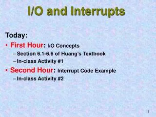
I/O and Interrupts. Today: First Hour : I/O Concepts Section 6.1-6.6 of Huang’s Textbook In-class Activity #1 Second Hour : Interrupt Code Example In-class Activity #2. Goal: Example Task.

I/O and Interrupts
E N D
Presentation Transcript
I/O and Interrupts • Today: • First Hour: I/O Concepts • Section 6.1-6.6 of Huang’s Textbook • In-class Activity #1 • Second Hour: Interrupt Code Example • In-class Activity #2
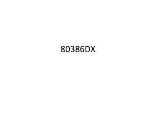
Goal: Example Task Read the output of the 4-bit data source every time the push button is pressed, and display the result. Computer (HC11 chip) 4-bit Data Source Display Push Button
HANDSHAKE I/O DATA DIRECTION C PARALLEL I/O PORT B PORT C P P P P P P P P P P P P P P P P S S SINGLE B B B B B B B B C C C C C C C C T T CHIP 7 6 5 4 3 2 1 0 7 6 5 4 3 2 1 0 R R B A A A A A A 1 1 1 1 1 5 3 2 4 M6811 Ports PA7 PAI ROM-8KB PULSE ACCUMULATOR OC2 O PA6 C OC3 PA5 1 PORT PA4 OC4 RAM-256 bytes OC5 A PA3 IC1 PA2 PERIODIC INTERRUPT PA1 IC2 EEPROM-512 bytes COP WATCHDOG IC3 PA0 PE7 PD5 SS SCK PD4 PE6 SPI PE5 MOSI PD3 PORT PE4 PD2 MISO PORT DATA DIRECTION A/D E PE3 D CONVERTER PE2 PD1 TxD SCI PE1 RxD PD0 PE0 V REFH M68HC11 CPU V REFL ADDRESS DATA BUS RESET INTERRUPTS XIRQ IRQ (V ) PPBULK XTAL OSCILLATOR EXTAL E MODA MODE LIR SELECT MODB (V ) STBY A A A A A A A A A A A AS 1 9 8 D D D D D D D D R/W V EXPAND DD 1 0 7 6 5 4 3 2 1 0 POWER V SS
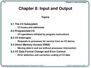
Way to read/write from/to peripheral devices Some ports allow both input and output (see your PRG!) Each port has: Control Registers Status Registers Data Registers Data Direction Registers The ports are memory mapped, which means that you can access these registers via memory! I/O becomes a simple matter of reading/writing to these special memory locations! Ports
6811 Parallel I/O Using Ports Look up PRG! - The 68HC11A8 has 40 I/O pins that are arranged in five I/O ports. - All I/O pins serve multiple functions. - Ports C and D are bi-directional I/O pins under the control of their associated data direction registers. - Port C, port B, the STRA pin, and the STRB pin are used for strobed and handshake parallel I/O, as well as for general-purpose I/O. Port Registers - To input, the 68HC11 reads from the port data register - To output, the 68HC11 writes into the port data register - All except port C have one data register: PORTA (at $1000) PORTB (at $1004) PORTC (at $1003) PORTCL (at $1005) PORTD (at $1008) PORTE (at $100A)
Data & Direction Registers • Each pin of ports C and D has an associated bit in a specific data register and another in a data direction register. • The primary direction of a pin is set by its associated bit in the data direction register. • When an output pin is read, the value at the input to the pin driver is returned. • The data direction registers are cleared by reset to configure all bi-directional I/O pins for input. • - Before performing I/O operation to these two ports, the software should set up the data direction registers of these two ports.
Data & Direction Registers DDRC 0 4-bit Data Source 0 0 0 0 1 1 1 1 P O R T C 3 4 7 Display
Eg: Setting I/O Pin Directions PORTC Example Program Fragment PORTC EQU $1003 DDRC EQU $1007 IO_PAT EQU %11110000 NUMBER EQU %10010011 ... LDAA #IO_PAT STAA DDRC LDAA #NUMBER STAA PORTC LDAA PORTC Which PORTC pins are Input: Output: ? [3:0] [7:4] What bit pattern is output: ? %1001
Eg: Output to Port D REGBAS EQU $1000 PORTD EQU $08 DDRD EQU $09 LDX #REGBAS LDAA #$3F ; directions of port D pins STAA DDRD,X LDAA #$CD ; output $CD to port D STAA PORTD,X
Parallel I/O Control Register - All strobed mode I/O and handshake I/O are controlled by this PIOC register 7 6 5 4 3 2 1 0 PIOC STAF STAI CWOM HNDS OIN PLS EGA INVB at $1002 value after 0 0 0 0 0 U 1 1 reset Strobe A flag STAF: . This bit is set when a selected edge occurs on the STRA signal. STAI: Strobe A interrupt enable . When the STAF and STAI bits are both equal to 1, a hardware interrupt request will be made to the CPU. . . . EGA: Active edge for STRA 0: falling edge 1: rising edge INVB: Invert STRB 0: STRB active low 1: STRB active high
Strobe Input Port C • Strobe is an external signal which can be used to trigger the I/O from the port. • Eg: Push botton ! • Strobe Setup: • Strobe mode I/O selected when the bit 4 (HNDS) of the PIOC register is set to 0 and port C becomes a strobe input port. • The bit 1 (EGA) of the PIOC register when set to 1 selects the active edge of the STRA pin. • The active edge of the STRA signal latches the values of the port C pins into the PORTCL register.
- Reading the PORTC register returns the current values on the port C pins. Reading the PORTCL register returns the contents of the latched PORTCL. When enabled using bit 6 (STAI) of the PIOC, the active edge of the STRA signal will generate an interrupt to the 68HC11. This interrupt shares the same vector as IRQ. This can be used to force an interrupt-driven I/O ! Strobe I/O Port C (Contd)
Do Activity #1 Now Reference code REGBAS EQU $1000 PORTD EQU $08 DDRD EQU $09 LDX #REGBAS LDAA #$3F ; directions of port D pins STAA DDRD,X LDAA #$CD ; output $CD to port D STAA PORTD,X
Computer (HC11 chip) 4-bit Data Source Display Push Button Goal: Example Task Read the output of the 4-bit data source every time the push button is pressed, and display the result.
START BUTTON PRESSED? NO Computer (HC11 chip) 4-bit Data Source YES 1 ms delay Display BUTTON PRESSED? NO Push Button YES READ 4-BIT INPUT UPDATE DISPLAY Recap: Polling Method This style of computer input/output is called Polled I/O because we’re constantly polling the pushbutton
The CPU is temporarily interrupted. An Interrupt Service Routine is entered START INTERRUPT SERVICEROUTINE Key Pressed START INITIALIZE READ THE 4-BIT INPUT UPDATE THE DISPLAY DO SOMETHING USEFUL RETURNFROM INTERRUPT Recap: Interrupt Method START INTERRUPT SERVICEROUTINE READ THE 4-BIT INPUT UPDATE THE DISPLAY DO SOMETHING USEFUL RETURNFROM INTERRUPT The CPU now resumes where it left off!
Interrupt Details Done by hardware Identify source(s) Resolve priority Push registers Disable further interrupts Call interrupt service routine START Interrupt Request Initialize Stack Setup Interrupt Vectors Clear previous interrupts & initialize device keeping interrupts disabled START INTERRUPT SERVICEROUTINE Further identify source if needed Service interrupt Clear interrupt request flag* Enable interrupts locally at device Enable interrupts globally MAIN LOOP RETURNFROM INTERRUPT (RTI) Restore registers Enable Interrupts
The low nibble of PORTC is connected to a 7-segment display (output) The hi nibble of PORTC is connected to a 4-bit thumbwheel switch (input) The STRA line is connected to a high-asserting pushbutton Problem : Copy thumbwheel setting to display whenever pushbutton is pressed. This program should run on the EVB Also illustrates the general form of programs using interrupts. Task: Hardware Setup
*Equates: define symbolic names for registers and constants PIOC EQU $1002 PORTC EQU $1003 DDRC EQU $1007 PORTCL EQU $1005 VECLOC EQU $00EE ; see EVB manual sec 3.3 the STRA line generates an IRQ interrupt JMPOP EQU $7E ; opcode for extended jmp IOPAT EQU $0F ; for data direction reg CTRPAT1 EQU %00000011 ; for PIOC reg, STAI disabled CTRPAT2 EQU %01000011 ; for PIOC reg, STAI enabled * Data Section - setup stack space and initial Stack Pointer ORG $D000 STACK RMB $7FF INITSP EQU *-1 Code: initialization
* Setup and Initialization Program ORG $C000 * initialize stack pointer SETUPINT LDS #INITSP * initialize PORT C and associated control registers LDAA #CTRPAT1 ; STAI (temporarily) disabled STAA PIOC LDAA #IOPAT ; $0F =>lower nibble output ; higher nibble input STAA DDRC CLR PORTC ; Clear Port C Code: Init Port C
*setup interrupt vector in Buffalo jump table. *See section 3.3 of EVB manual for details. LDAA #JMPOP ; Load the Opcode for JMP ; at this vector location STAA VECLOC LDX #ISRIRQ ; Load the 16-bit RAM Address ; for the IRQ ISR (which is ; shared by STRA) in the next ; 2 bytes. STX VECLOC+1 ; Total:3 bytes per IVT location Code: Setup Software IVT
*clear status of peripheral or subsystem that could cause *an immediate interrupt. See 6811 Reference manual Section 5.7, * Also see the textbook. LDAA PIOC LDAA PORTCL * Enable Interrupt in peripheral or subsystem LDAA #CTRPAT2 ; STAI enabled STAA PIOC * Enable Interrupts globally CLI ; Clears I-bit in CCR. 0 => enable * Jump to main program JMP MAIN ****************************************************** * MAIN PROGRAM: trivial ****************************************************** MAIN BRA MAIN Code: Enable Interrupts; Main
On entry, all registers (incl. CCR with I bit) have been pushed on stack, and the I bit is set to 1 to mask further interrupts. * First check for valid interrupt. Branch to RTIIRQ if invalid. ISRIRQ LDX #PIOC BRCLR 0,X %10000000,RTIIRQ * Execute the unique recipe for clearing device interrupt flag LDAA PIOC LDAA PORTCL ; Wacky !! * Service interrupt RORA RORA RORA ; Rotate 4 times RORA ; Low nibble now has the 4 bits! STAA PORTC ; Output to 7-segment display * Return from interrupt service routine RTIIRQ RTI ; restore registers and return to main * Note that this restores CCR (hence I bit), re-enabling interrupts. END Interrupt Service Routine
Do Activity #2 Now • Due: End of Class Today. • RETAIN THE LAST PAGE(S) (#3 onwards)!! • For Next Class: • Bring Huang Textbook, & HC11 PRG • Required Reading: • Sec 4.1-4.7 of Huang • This reading is necessary for getting points in the Studio Activity!