Download

1 / 57
570 likes | 787 Views
Fiber Optic Communication By. Engr. Muhammad Ashraf Bhutta. SDH Overview Frame structure and multiplex-ing methods Overheads and Pointers. Lecture Outlines. SDH Overview. Background of SDH. Advantages of SDH. Disadvantages of PDH. Disadvan-tages of SDH.

E N D
Fiber Optic CommunicationBy Engr. Muhammad Ashraf Bhutta
SDH Overview Frame structure and multiplex-ing methods Overheads and Pointers Lecture Outlines
SDH Overview Background of SDH Advantages of SDH Disadvantages of PDH Disadvan-tages of SDH
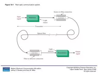
Background about SDH emergence What is SDH--Synchronous Digital Hierarchy. Similar to PDH,they are all digital signal transmission system. Why did SDH emerge? 1)What we need in info-society: huge volume of info, and digital, integrated, personal. 2)What we want the transmission network to be: Broadband---info-highway Standard---universal interface all over the world
Disadvantages of PDH: 1 Interfaces Electrical interfaces---only regional standards, no universal standard. 3 rate hierarchies for PDH:European(2Mb/s) Japanese, North American(1.5Mb/s). Optical interfaces---no standards at all, manufacturers develop at their will.
Multiplexing methods: Asynchronous Multiplexing for PDH: The location of low-rate signals in high-rate signals is not regular nor predictable. So it is impossible to directly add/drop low-rate signals from high-rate signals. Where did I put the signals?
Low-rate signals have to be separated from high-rate signals level by level. Multiple levels of multiplexing/de-multiplexing cause signals to deteriorate, it is not suitable for huge-volume transmission.
OAM OAM function affects the maintenance cost.It is determined by the number of overhead bytes(redundant bytes); There are VERY few redundant byes available in PDH signals which can be used as OAM purpose, so OAM in PDH is very poor, it is unreliable either. 4 No universal network management interface It is hard to set up an integrated network management. No way to form a universalTMN. PDH is inappropriate to transmit huge-volume signals, so SDH came to play the part.
Advantages of SDH: 1 Interfaces Electrical interfaces:standard rate hierarchy(transmission speed level) The basic rate level is called Synchronous Transfer Module(STM-1), the other rate levels are the multiple of STM-1. Optical interfaces:only scramble the electrical signals. SDH: optical code pattern is scrambledNRZ, PDH: optical code pattern is scrambledmBnB.
SDH Signals Bit rate(Mb/s) STM-1 155.520 or 155M STM-4 622.080 or 622M STM-16 2488.320 or 2.5G STM-64 9953.280 or 10G SDH:high-rate signal is exactly 4 times that of the next low-rate signal.
STM-1 STM-4 STM-1 STM-1 STM-1 2 Multiplexing methods: low-rate SDH→high-rate SDH(e.g.:4 STM-1→STM-4). Uses byte interleaved multiplexing method. Byte interleaved multiplexing
PDH Pkg STM-1 Packing Alignment PKG b PKG a Other signals→SDH: Using pointers to align the low-rate signals in SDH frame ,so the receivers can directly drop low-rate signals.E.g.:
3 OAM More bytes in SDH frame structure are used for OAM purpose, about 5% of total bytes. SDH boasts of high capability of OAM. 4 Compatibility SDH is compatible with the existing PDH system. SDH allows new types of equipment to be used, allows broadband access, such as ATM.
SDH compatibility schematics PDH, ATM FDDI signals packing SDH network Package package STM-N STM-N packing transmit transmit transmit unpacking PDH, ATM FDDI signals
632M 2M STM-1 (155M) 334M=482M 34M 140M 1140M=642M Disadvantages of SDH 1 low bandwidth utilization ratio--- contradiction between efficiency and reliability. 2 Mechanism of pointer adjustment is complex, it can cause pointer adjustment jitters 3 Large-scale application of software makes SDH system vulnerable to viruses or mistakes.
140M STM-N 34M 2M Frame Structure and Multiplexing methods Multiplexing Procedure Components and functions
STM-N Frame Structure 9×270 ×N bytes Transmission direction 1 Transmit left to right up to down SOH 3 4 AU-PTR STM-N payload (including POH) 5 SOH 9 9×N 261×N 270×N columns
1 Characteristics of SDH signals: block frame in units of bytes(8bit), transmission---from left to right, from top to bottom, frame frequency constant---8000 frames/s, frame period 125us. 2 Composition of SDH signals: 1) Payload: It is where we put all the information in STM-N frame structure. All kinds of effective info, such as 2M, 34M , 140M are first packed before being stored here. Then they are carried by STM-N signals over the SDH network.
If we should consider STM-N signal to be a truck, then info payload would be the carriage of the truck. In order to monitor the transmission status of the goods during transportation, POH are added to each information package. STM-N POH Pkg Pkg Pkg loading Low-rate signals 1 Payload packing Low-rate signalsn Pkg Pkg Pkg loading packing POH
2) Section Overhead: Accomplishes monitoring of STM-N signal streams. To check whether the “goods” in STM-N “carriage” is damaged or not. Regenerator Section Overhead(RSOH): monitor the overall STM-N signals. Multiplex Section Overhead(MSOH): monitor each STM-1 in STM-N signal. RSOH, MSOH and POH set up SDH layered monitoring mechanism.
Sections and Paths Low-rate signal 1 SDH Section signal (SOH) . Low-rate signal 2 Low-rate signal n low-rate path signal(POH)
3) Administrative Unit Pointer(AU-PTR): Indicates the location of low-rate signals in STM-N frame(payload), makes the location of low-rate signals in high-rate signals predictable.
According to the value of AU, the receiver can directly drop low-rate signals from STM-N frame. That is to say we can get the “goods” directly from the “carriage” if we know the label of the “goods”. Because the “goods” are placed regularly in the “carriage”, we only need to know the first piece of “goods”.
键入文本 键入文本 键入文本 键入文本 键入文本 键入文本 键入文本 键入文本 键入文本 键入文本 键入文本 键入文本 键入文本 键入文本 键入文本 键入文本 键入文本 键入文本 键入文本 键入文本 键入文本 键入文本 键入文本 键入文本 键入文本 键入文本 键入文本 键入文本 键入文本 键入文本 键入文本 键入文本 键入文本 键入文本 键入文本 键入文本 键入文本 键入文本 键入文本 键入文本 Receiving: According to the value of AU-PTR, get the first info package, through the regularity of byte interleaved multiplexing, get the other packages Sending: AU-PTR indicates the first info package (SDH transmission network)
AU-PTR Secondary alignment 2M 34M TU-PTR Primary alignment For low-rate signals such as 2M, 34M. We need two-levels of pointers to align. First, small information “goods” is packed into middle information “goods”. Tributary unit pointer(TU-PTR) is used to align the location of small “goods” in middle “goods”. Then these middle “goods” are packed into big “goods”, AU-PTR is to align the location of middle info package.
Multiplexing procedures of SDH low-rate SDH→high-rate SDH: byte interleaved multiplexing, 4 into 1. PDH signals→STM-N: synchronous multiplexing: 140M→STM-N 34M→ STM-N 2M→STM-N Multiplexing is based on the multiplexing route diagram. ITU-T defines several different multiplexing routes, but for any country or region, the method is unique.
AU-4 TU-3 TU-12 SDH Multiplexing Hierarchy ×N 139264kbit/s STM-N AUG VC-4 C-4 ×3 SDH signal VC-3 TUG-3 ×7 34368kbit/s C-3 Pointer processing TUG-2 ×3 Align adjustment 2048kbit/s VC-12 C-12 Multiplexing Mapping PDH signals
140M multiplexing procedures(140M →STM-N) 1 1 P O H Rate Adaptation POH C4 VC4 To be continued 140M 9 9 1 260 1 261 125us 125us C4---Container 4: A standard info structure corresponding to 140M, performs bit rate justification. VC4---Virtual Container 4: A standard info structure corresponding toC4, performs real-time performance monitoring of 140M
AU-4---Administrative Unit 4, a info structure corresponding toVC4, performs pointer alignment. 140M—VC4—AU-4—STM-1, One STM-1 can only incorporate one 140M signal. 140M multiplexing procedures AU-4 STM-1 1 1 (continue) RSOH payload AU-PTR 1 270xN alignment SOH AU-PTR 1 1 9 MSOH 9 9 10 270 1 270 STM-N 125us 125us 9 125us
34M multiplexing procedures C3 VC3 1 1 P O H POH Rate adaptation To be continued 34M 9 9 1 84 1 85 125us 125us C3---Container 3: A standard info structure corresponding to 34M, performs bit rate justification. VC3---Virtual Container 3: A standard info structure corresponding to C4, performs real-time performance monitoring of 140M
VC4 TU-3 TUG-3 1 86 1 86 1 261 (continue) H1 H2 H3 1 1 1 H1 H2 H3 R ×3 P O H TU- PTR Fill Gap R R BIM 9 9 9 125us 125us 125us TU3---Tributary Unit 3: A standard info structure corresponding to VC3, performs primary alignment. TUG3---Tributary Unit Group 3: A standard info structure corresponding toTU3. 34M—VC3—TU3—TUG3;3 TUG3—VC4—STM-1; One STM-1 can hold 3 34M. 34M multiplexing procedures
2M multiplexing procedures POH 1 1 1 Primary Alignment C12 Rate Adaptation VC12 TU12 POH To be continued 2M 9 PTR 9 9 1 4 1 4 1 4 125us 125us 125us
2M multiplexing procedures (2M →VC4) C12--Container 12: A standard info structure corresponding to 2M, performs bit rate justification for 2M signals, 4 basic frames constitute a multi-frame. VC12---Virtual Container 12:A standard info structure corresponding to 2M, performs real-time monitoring. TU12---Tributary Unit 12: A standard info structure corresponding to VC12, performs primary pointer alignment forVC12.
2M multiplexing procedures (2M →VC4) 1 86 1 1 1 ×3 ×7 Byte Interleaved Multiplexing TUG2 Byte Interleaved Multiplexing TUG3 R R (continue) 9 9 125us 125us
2M Multiplexing procedures(2M →VC4) TUG2---Tributary Unit Group 2 TUG3---Tributary Unit Group 3 2M—C12—VC12—TU12;3TU12—TUG2; 7 TUG2—TUG3;3TUG3—VC4—STM-1。 One STM-1 is able to hold 3×7×3= 63 2M. Multiplexing structure for 2M is 3-7-3.
1# STM-1 STM-1 2# STM-1 3# STM-1 4# SDH Multiplexer 63 2M 1# C12 C12 2# C12 3# C12 4# Concept of multi-frame: 4 C12 basic frames make up 1 multi-frame. Both basic frames and multi-frame carry the same 2M signal. One basic frame can hold the info segment of 2M signal during 125us period. One multi-frame holds the info for 2M signal during 500us period.
E1 C12 TU12 VC12 E3 C3 VC3 TU3 C4 VC4 E4 Relations between info structures
Summary STM-N frame structure and functions of different parts of the frame Methods for multiplexing PDH intoSTM-N frames 140M multiplexed into STM-N frames 34M multiplexed into STM-N frames 2M multiplexed into STM-N frames
Overhead and Pointers Overhead Pointers Path Overhead Section Overhead AU-PTR TU-PTR
Overhead SOH POH RSOH MSOH VC4 POH VC12 POH (LPOH) (HPOH)
SOH(take STM-1 as an example) 1 2 3 4 5 6 7 8 9 1 2 3 4 5 6 7 8 9 A1 * A1 * A1 * A2 * A2 * A2 * J0 * * * B1 E1 F1 RSOH D1 D2 D3 AU-PTR B2 B2 B2 K1 K2 D4 D5 D6 D7 D8 D9 MSOH D10 D11 D12 S1 M1 E2 Bytes reserved for domestic use Marked bytes are not scrambled *
Signal stream STM-N STM-N STM-N STM-N STM-N STM-N 1) Framing bytes:A1,A2 to locate the frame heads
Frame Head? N Found A1,A2? Give OOF Y Over 3ms Generate LOF Next process Insert AIS
2) DCC Data Communication Channel bytes:D1—D12 An info channel for OAM between NE-NE D1-D3 is in Regenerator section(DCCR), D4-D12 is in Multiplex section(DCCM), UTP DCC channel NM OAM info includes: performance monitoring, alarms inquiry, command issue,etc.
3) Order wire bytes: E1,E2 Each provides a 64kb/s order wire digital telephone. E1is for RS order wire E2 is for MS order wire E2can not be used by a REGs 4) Bit interleaved parity byte:B1 Performs real-time monitoring over the signal stream
B1 working mechanism: Detect B1 Insert B1 SDH Equipment Sending SDH Equipment Receiving STM-N If error blocks occurred produce: RS-BBE performance event