Download
1 / 36
370 likes | 511 Views
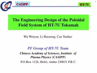
HT-7U. The Engineering Design of the Poloidal Field System of HT-7U Tokamak. Wu Weiyue, Li Baozeng, Cao Yunluo. PF Group of HT-7U Team Chinese Academy of Sciences, Institute of Plasma Physics (CASIPP) P.O.Box 1126, Hefei, Anhui 230031 P.R.C. 1. Main parameters of HT-7U

E N D
HT-7U The Engineering Design of the Poloidal Field System of HT-7U Tokamak Wu Weiyue, Li Baozeng, Cao Yunluo PF Group of HT-7U Team Chinese Academy of Sciences, Institute of Plasma Physics (CASIPP) P.O.Box 1126, Hefei, Anhui 230031 P.R.C.
1. Main parameters of HT-7U 2. PF coils position & size 3. Conductor design 4. Winding & insulation 5. Analysis on strength of the magnets & structure 6. Fabrication & testing 7. Outlook for the near future
1. Main Parameters of HT-7U Major Radius, Ro1.79 ~ 1.96 m Minor Radius, a0.4 ~ 0.55 m Plasma Current, IP1 MA Elongation, Kx1.6 ~ 2 Triangularity, dx0.6 Toroidal Field, Bt 3.5 T Plasma Duration~ 1000 s Configuration:Pump limiter Double null Single null Heating and Driving: LHCD3.5 MW ICRH3~3.5 MW ECRH0.5 MW
7600mm H13300mm 7095mm HT-7U Tokamak 3430mm 2500mm
2. PF Coils Position and Size Center of the device Equator plane All PF coils are placed symmetrically about the equator plane
6.65m 6.47m PF Magnets System of HT-7U
Bh(cm) No. R(cm) Z(cm) Nr Nz Bw(cm) 1 56.404 4.1085 7 20 2.154 2.213 2 56.404 54.3725 7 20 2.154 2.213 3 56.404 104.6365 7 20 2.154 2.213 4 96.447 172.05 11 4 2.154 2.213 5 96.447 181.921 17 12 2.154 2.213 6 289.623 149.92 6 10 1.974 2.034 324.019 83.3 4 8 1.974 2.034 7 Parameters of PF coils
3. Conductor for PF coils NbTi strands(UNK) with segregated copper is chosen for all PF coils The configuration of the PF CICC Ⅰ(for PF1-5)
Parameters about PF CICC PF1-PF4PF5-PF6 Strands conf.(2SC+2Cu)34(5+1) (1SC+2Cu)34(5+1) No. of Sc strand120 60 No. of Cu strand141(Φ0.98)120(Φ0.98)+21(Φ0.87) Surface Coating with Ni 2m Pb-Sn-Sb3m Peak field4.5T >2.5T CICC size20.4mm×20.4mm 18.6mm×18.6mm Conduit material316LN 316LN Conduit thickness1.5mm 1.5mm Current (Io) 14.5kA 14.5kA f(Io/Ic) 0.224 0.31 Temperature Margin(ΔTs) 2.24K 1.99K Stable margin(ΔE) 350mJ/cm3 400mJ/cm3
4. Winding and insulation Turns insulation 2 layers kapton 0.06mm, fiberglass 0.44mm; Pancake insulation 0.84mm fiberglass carpet; Ground insulation 5mm fiberglass wrapping; Vacuum pressure impregnates with epoxy resin
PF coil’s winding structure Turns 140 (1 CICC) Inner Radius 55cm Outer Radius 71cm Height 46cm CICC Length 565m (no joint)
View of one piece central solenoid coil 0.45m 1.1m 7 20=140 turns 2 current terminates 4 cooling tubes Cooling channel L is 130m (28 turns) 0.16m
5. Analysis on magnets strength and structure 6 coils through bolts preloading; Height is 4 m; Total is 6140=840 turns 4m Solenoid Coils Assembly
Helium tubes Current terminates 1.87m Helium tubes in a different angle with the current terminates about 45 degree; 6 coils are set in different angle each other also, according to the terminates and helium tubes. Top view of central solenoid
PF coils current waveforms for the basic scenarios Plasma current Ip ignition OH discharge OH charge end
Electromagnetic Force on solenoid are different on each coil and in each moment. Fr Fz Analysis on the structure for the preloading force and Electromagnetic Force on support parts of the assembly solenoid. Moment Fr Fz Moment Fr Fz Moment
6.1mm & 279 MPa 0.3mm & 16 MPa 47.5 MPa The results show the design on strength is suitable and safety enough.
6. Fabrication and testing for PF system A central solenoid model coil (CSMC) had been fabricated in 2000 & tested in 2001. CSMC after winding CSMC with supports
Parameters of CSMC Turns 914=126 Inner radius 37.6cm Outer radius 57.3cm Height 28.6cm CICC length 368m Inductance 15.4mh Cooling channel 365m Ioperating 14.5/18KA Peak field 5T Stored energy 1.62/2.5MJ Parameters of solenoid Turns 720=140 Inner radius 55cm Outer radius 71cm Height 46cm CICC length 565m Inductance 26mh Cooling channel 130m Ioperating 14.5KA Peak field 4.5T Stored energy 2.74MJ
Test Facility Parameters Din 3.1 m Hin 4.7 m Vacuum 1×10⁻⁵torr Current leads 2 pairs Imax. 30 kA Refr. 500W/4.5k Topr. 4.5/3.8K
4 days cooling down for CSMC in 1st testing Part view next
Resistance disappeared in 2 days from 6.5m Part view next
Several types CICC have been fabricated 6 types CICC cabling in VNIIKP(Russia) and jacketing in CASIPP More than 8 types CICC with different configuration have been designed and made during past three years. 2 types CICC was made in China(including cabling)
Two pieces 600m CICC has been fabricated in CASIPP this year
7. Outlook for PF system • The final design of the PF system will be finished this year. • One section of central solenoid coils will be fabricated and tested in the end of this year. • All the components(coils, structure and connecting parts) of PF system will be fabricated completely in next year. The assembly central solenoid will be testing with the structure and preloading. • The assembly of HT-7U device is planed to start in next year.
HT-7U device will be build in Institute of Plasma Physics, Chinese Academy of Sciences(CASIPP) Sciences Island
That's all. Thank you !
Parameters of NbTi Strands (UNK) Diameter ф0.87mm Critical current (Ic)500A(4.5K,5T) 426A(4.5K,5.8T) Number of SC filaments8910 Diameter of SC filament6μm twist10mm Ratio of s. cu1.38:1 • Polyamide+Vacuum Pressure Impregnates • No strands splice • No lubricant