數位IP設計實務 三 - Verilog 硬體語言模擬
數位IP設計實務 三 - Verilog 硬體語言模擬. 工業技術研究院 趙仁偉 wayne.chao@ itri.org.tw. Agenda. 為什麼要做模擬 測試模組 (test module) 寫法 ModelSim 模擬軟體 其他模擬除錯軟體 進階測試模組撰寫 設計測試範例解說. 為什麼要做模擬. RTL (Register Transfer Level) simulation Pre-sim 和 post-sim 不在目前我們討論範圍 驗證設計模組 (design module) 的電路行為 觀察波形 (check waveform)

數位IP設計實務 三 - Verilog 硬體語言模擬
E N D
Presentation Transcript
數位IP設計實務三- Verilog硬體語言模擬 工業技術研究院 趙仁偉 wayne.chao@itri.org.tw
Agenda • 為什麼要做模擬 • 測試模組(test module)寫法 • ModelSim模擬軟體 • 其他模擬除錯軟體 • 進階測試模組撰寫 • 設計測試範例解說
為什麼要做模擬 • RTL (Register Transfer Level) simulation • Pre-sim和post-sim不在目前我們討論範圍 • 驗證設計模組(design module)的電路行為 • 觀察波形(check waveform) • 用人眼確認數位訊號0與1 • 測試結果樣本比對(pattern comparison) • 將電路輸出成文字檔案與系統模擬(C或Matlab)比較 • 模擬涵蓋度(code coverage) • 區塊涵蓋度(block coverage) • begin-end block • 表達敘述涵蓋度(expression coverage) • assign a = b ? c : d • 觸發涵蓋度(toggle coverage) • wire [3:0] a
測試模組(test module)寫法(1/5) • 測試模組『包裝』設計模組 • 測試模組提供『刺激』(stimulus)測試向量 • 測試模組『收集』電路輸出結果
測試模組(test module)寫法(2/5) • 時間單位精準度(timescale)宣告 • `timescale <time_unit>/<time_precision> • Ex. `timescale 1ns/10ps • 測試模組名稱與宣告 • 測試模組沒有in/out port名稱 • 只有wire/reg連接『設計模組』 • 宣告reg訊號連接『設計模組』的輸入 • 宣告wire訊號連接『設計模組』的輸出
測試模組(test module)寫法(3/5) • 宣告時脈(clock) • always #5 chip_clk =初始 ~chip_clk; • 測試『刺激』(stimulus)區塊 • initial begin….end block • 設定reg(亦即設計模組的輸入)的初始值(initial value) • 設定經過多少時間後,各訊號的變化 • #10 in1=1’b1; in2=1’b0; • 結束模擬 • $finish
測試模組(test module)寫法(4/5) • 儲存訊號波形檔 • 用於使用Debussy nWave觀看波形結果時 • $fsdbDumpvars(0, TestModule); • $fsdbDumpfile(“xxx.fsdb”); • 儲存一般公用格式VCD (Value Change Dump) • $dumpvars(0 , TestModule); • $dumpfile(“xxx.vcd”); • 儲存pattern檔案 • 開檔: file_ptr = $fopen(“D:\xxx.txt”); • 關檔: $fclose(file_ptr);
測試模組(test module)寫法(5/5) 測試模組 • 測試模組範例 設計模組
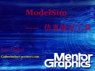
ModelSim模擬軟體 (1/4) Compile your design with testbench
ModelSim模擬軟體 (2/4) Load the design: your testbench
Debussy 除錯軟體 – Import Design 選擇 Import Design
Debussy 除錯軟體 – Add Files step1 step4 step3 step2 step5
Debussy 除錯軟體 –Load Simulation Results 選擇 Load Simulation Results
Debussy 除錯軟體 – Select fsdb File step1 step2 step3
Debussy 除錯軟體 – Add Signals (2/4) 方法1 : 直接選取Signals 拖曳至nWave視窗中 按住滑鼠中鍵拖曳至nWave視窗中
Debussy 除錯軟體 – Add Signals (2/4) 方法2 : 由Get Signals視窗選取 step4 step1 step2 step3
Debussy 除錯軟體 – Add Signals (3/4) 方法2 : 由Get Signals視窗選取
其他模擬除錯軟體 • 除了ModelSim外的模擬和除錯軟體選擇 • Verilog-XL • 比較舊的模擬軟體,廠商(Cadence)可能已無更新維護 • NC-Verilog(NC-Sim) • 目前業界比較認同的sign off模擬軟體 • Debussy nWave • 目前業界公認最好用的除錯看波形軟體 • 儲存的波形格式FSDB比傳統VCD檔案size小很多 • 但對於VHDL訊號的支援較差 • 例如:VHDL的『variable』
NC-Verilog模擬軟體(1/2) • ncvlog • 分析(analyze)和編譯(compile) Verilog程式碼 • ncelab • 闡述鋪陳(elaborate) 電路設計的階層性(hierarchy),決定模型(model)以利後續產生模擬快照(snapshot) • ncsim • 進行電路模擬,可控制時間長短、強制輸入、結束等功能 • 儲存訊號波形檔案 • A file containing the logic states of selected signals from a simulation run. The NC Verilog simulator supports the Simulation History Manager (SHM) and the Value Change Dump (VCD) database formats.
NC-Verilog模擬軟體(2/2) Command style ncverilog +access+r TestMyAnd2.v MyAnd2.v ncverilog +access+r \ TestMyAnd2.v \ MyAnd2.v Another command style Save as an executive file or Makefile Output log (check compile error or warning!) go.bat or Makefile ………….. $dumpvars(hierarchical_level, instance_name); ………….. Add waveform command ncverilog.log Generate VCD format verilog.dump
Debussy nWave除錯軟體(1/2) Command style nWave verilog.dump Open VCD database & translate to fsdb file verilog.dump.fsdb Get signals 使用Debussy PLI直接在測試模組儲存FSDB格式檔案
Debussy nWave除錯軟體(2/2) 檢查設計波形結果: reset, clock, 其他輸入輸出訊號
進階測試模組撰寫 • 擴展測試程式碼作自我比對 • 增加輸入測試向量(test pattern)檔案 • 與系統模擬使用相同的輸入測試向量 • 可做較完整測試 • 儲存輸出結果成檔案(dump file) • 輸出與期望結果比較
擴展測試程式碼作自我比對 • 利用$display搭配if-else判斷 • 模擬時輸出『對』或『錯』的訊息在log檔 // Test flow initial begin $fsdbDumpvars(0, TestMyAnd2); $fsdbDumpfile("test.fsdb"); a=0; b=0; // Begin to change inputs. #30 a=1; #20 a=1; b=1; if (c=0) $display(“%0t Error output!”, $time); else $display(“Correct output”); #20 a=0; // End of simulation. #20 $finish; end
增加輸入測試向量(test pattern)檔案(1/2) • 定義輸入檔案 • 宣告輸入測試向量暫存器和讀取位址(address) • 使用system task ($readmemb或$readmemh)來讀取輸入檔案內容 • 在測試模組中加入讀取位址遞增的段落,並指定讀入資料的去處
增加輸入測試向量(test pattern)檔案(2/2) // define input file path and length `define INPUT_PATTERN_NUMBER 1024 `define INPUT_FILE "./pattern/input.txt“ …………………. // declare input pattern registers & reading address reg [4:0] input_rom [0:`INPUT_PATTERN_NUMBER-1]; integer input_rom_addr; …………………. $display(" Now Read input patterns ..."); $readmemb(`INPUT_FILE, input_rom); …………………. always @ (posedge clk) begin // assign input pattern & increase pattern address input_rom_addr <= #1 input_rom_addr + 1; internal_in <= #1 input_rom[input_rom_addr]; end
儲存輸出結果成檔案(dump file) (1/2) • 定義輸出檔案 • 宣告輸出檔案指標(pointer) • 使用$fopen來開啟輸出檔案,回傳值送給輸出檔案指標 • 使用$fdisplay來將結果寫到輸出檔案內,最後用$fclose來關閉輸出檔案
儲存輸出結果成檔案(dump file) (2/2) // define output file path `define OUTPUT_FILE "./pattern/output.txt“ …………………. // declare output file pointer integer output_fp; …………………. $display(" output file initializing... ."); output_fp = $fopen(`OUTPUT_FILE); if (output_fp==0) begin $display("Error: Can’t open %s for output !\n",`OUTPUT_FILE); $finish; end …………………. // dump specified signals to a output file always @ (negedge clk) begin if (we) $fdisplay(output_fp,"%h", signal_out); end
設計測試範例解說(1/2) • 3GPP WCDMA Downlink Scrambling Code Generator • Initial conditions: • x is constructed with x(0)=1, x(1)= x(2)=...= x (16)= x (17)=0. • y(0)=y(1)= … =y(16)= y(17)=1
設計模組(1/2) • 檔頭、模組宣告、輸入輸出宣告
設計模組(2/2) • 電路設計:組合電路和序向電路
測試模組(1/3) • 定義和宣告
測試模組(2/3) • Instance, clock and dump/display
測試模組(3/3) • 測試流程和波形儲存