Download
1 / 33
330 likes | 438 Views
Join Team 05101 of the Formula SAE project to develop advanced driver aids for racecars, enhancing control and performance through innovative paddle and button shifters integrated with pneumatic systems. Discover the technical concepts and methods driving this cutting-edge project.

E N D
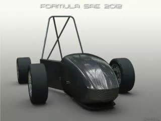
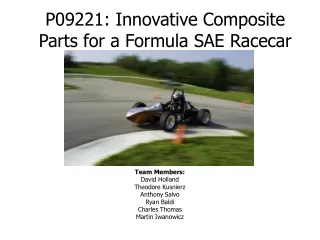
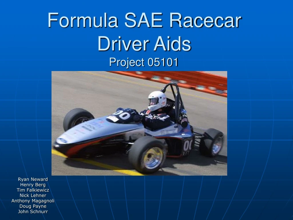
Formula SAE Racecar Driver AidsProject 05101 Ryan Neward Henry Berg Tim Falkiewicz Nick Lehner Anthony Magagnoli Doug Payne John Schnurr
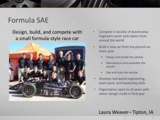
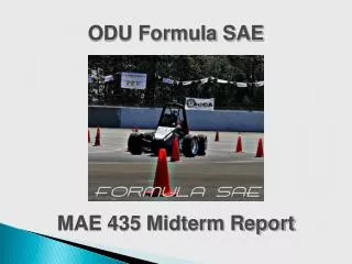
Background • Formula SAE team – comprised of SAE student members. • Objective: to build a Formula style race car, in the period of about one year, to participate in international competition where they must compete in a variety of static and dynamic events. • Project 05101: Formula SAE – Driver Aids • Objective: to add paddle and button shifters to the steering wheel so that the driver does not have to remove his hands from the wheel. The gear shift will be actuated by a pneumatic system, which will allow for other systems to be integrated; including flat shift and automatic up-shift systems.
Team Team Leader Ryan Neward - ME Scheduling Overall Project Needs Henry Berg - EE Nick Lehner - ME Pneumatic System Tim Falkiewicz - ME Mechanical Aspects Steering Wheel Design Anthony Magagnoli - ME Controller Doug Payne - ME Electrical Aspects Circuit Design John Schnurr - EE
Current Issues with the Car • Driver must remove hands from steering wheel to shift gears • Difficult to get optimal wheel spin when launching the car • Seating position relative to the steering wheel
Concepts • Types of Driver Aids Investigated • Types of Traction Control Investigated • Types of Paddle Shift Actuation Investigated
Types of Driver Aids Investigated • Traction/Launch Aid • Very useful, especially in acceleration events. • Paddle Shifting • Aids driver in all events. Hands can remain on steering wheel at all times, increasing control. • Flat Shift • Very useful with paddle shifting. Makes shifts faster, thus improves acceleration. • Automatic Up-shift • Improves acceleration by ensuring that all up-shifts occur at optimal RPM for acceleration event.
Traction/Launch Aids • Clutch Release Controlled • Not reliable, out of scope of project. • Brake Actuated • Heavy, complicated, expensive, hardware not available, possible rules conflict. • Throttle Controlled • Not allowed in rules (drive-by-wire). • Fuel/Spark Cut • Promising, but takes time to tune. • Dual Rev-Limit • Chosen for simplicity and reliability. Main focus of project is perfecting paddle shifting.
Shift Actuation Methods • Mechanical Linkage • Does not allow for automatic up-shift. • Electric Solenoids • Requires too much current. • Electro-Hydraulic • Too complicated, drains horsepower or current. • Electro-Pneumatic • Does not use horsepower or a large amount of current. Simpler, and allows for automatic up-shift.
Sponsor Goals • Shift the gearbox without driver removing hands from steering wheel using a non electrical method • Electronic flat shift • Automatic up-shift • Launch procedure for acceleration run
Completed Electro-Pneumatic System Needs Assessment • Shift actuation via Paddle and Button • Automatic up-shift Feature • Minimum of 750 shifts per charge • Maximum of 1 Amp average Power Consumption
Pneumatic Subsystem Component Constraints • Compressed Gas Storage Vessel • 4,500 psi, 44 cubic inches, Light Weight • Manifold and Solenoid • Cumulative Power drain under 1 amp. 3-positon 4-way configuration • Pneumatic Cylinder • Double Acting, with minimum force application of 20 lbs at a 1.6 inch moment arm • Pressure Regulator • Pressure range from 60-150 psi
Electrical Subsystem • Enable Switches • Automatic up-shift, Launch Control • Gear Selection Method • Paddle and Button • Gear Indicator • Dash hoop mounted LED array • Input/Output Capability • Transmission Drum Encoder, Relays, Switches • Intuitive Program • Ease of Modification • Power Constraints • 1 amp cumulatively
Paddle/Button Shifters • Paddles and buttons are built into the steering wheel • Driver operates a button or paddle to signal a shift • Controller receives shift signal • Controller activates pneumatic system
Flat Shifting • Controller receives up-shift signal • Controller then signals a relay that will cut the power to the fuel injector • Controller signals another relay to break the coils path to ground • After the shift is completed the relays are returned to their original position and normal engine operation resumes
Automatic Up-Shifting • A signal is sent from the RPM sensor to the controller • The signal is a square wave with a frequency that varies in proportion to the RPM • When a specified RPM is reached the controller activates the pneumatic system and an up-shift occurs
Two Stage Rev Limiter • System is activated by holding the rev limiter activation button • Relay connects the coolant temperature input of the ECU to ground • ECU sees the coolant temperature as 127°C • Rev limit table is setup so that at this temperature the maximum RPM are limited • When activation button is released the engine is allowed to resume normal operation
Gear Indicator • When the car is started the controller reads the current gear from the gear sensor • The LEDs corresponding to that gear are illuminated • After a gear shift occurs the controller updates the LED display with the current gear
Correct Shift Detection • After the controller requests a gear shift it reads the gear position from the gear sensor • If a gear change did not occur the controller requests another shift • This continues until the correct gear is reached or a set number of attempts have been made • This system also prevents an impossible shift request e.g. an up-shift request when the car is in top gear
Pneumatic System • This system is powered by a 1.5 L air tank that will be pressurized to 4500psi • A variable regulator fitted to the tank drops the pressure to the rest of the system to between 60psi and 150psi • A 4 way 3 position control valve allows air into the cylinder for up or down shifting when signaled by the controller • The cylinder is connected to the transmission and causes an up or down shift when air is allowed into either chamber
Flow Charts Launch Control Shift System
Finite life analysis Electrical components Component sizing Force requirement Tank and cylinder dimension variation Analysis & Synthesis 2186
Future Plans • Finished, working system in May • Paddle shifters - Majority of time • Pneumatic system • Flat shift - Testing • Automatic Up-shift - Integration • Launch Procedure - Testing
Options for Compressed Gas • Carbon dioxide • Freezes at relatively high temperature • Liquid when compressed • High pressure air • Can be filled to pressures of 4500 p.s.i. • Clean • Argon • Same properties as high pressure air • Can only be filled to 2200 p.s.i.
Specifications • System as a whole • Must abide by SAE rules • Cannot draw more than 1 amp • Temperature range from 20º to 120º F • Must be weather proof (snow, rain) • 750 shifts per tank, preferably 2500 shifts