System Clocks
310 likes | 539 Views
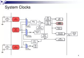
System Clocks. System Clocks. The LPC23xx has two main internal clocks. The first is Cclk, the CPU clock, which is used to clock the ARM7 CPU and the AHB peripherals which include the USB controller, Ethernet controller and the general purpose DMA.

System Clocks
E N D
Presentation Transcript
System Clocks • The LPC23xx has two main internal clocks. • The first is Cclk, the CPU clock, which is used to clock the ARM7 CPU and the AHB peripherals which include the USB controller, Ethernet controller and the general purpose DMA. • The second internal clock is Pclk, the peripheral clock, which is used to clock all the peripherals on the APB bus. • Both of these clocks may be derived from one of three oscillator sources, an internal RC oscillator, an external main oscillator and an external watch crystal.
System Clocks 32kHz - 50MHz For the MCB2300 board, OSC = 12MHz (Xtal oscillator) SYSclock = 2 x M x OSCin / N SYSclock= 2 x 12 x 12 / 1 = 288MHz
CPU, USB and Peripheral Clocks The output from the PLL enters a series of dividers that are used to determine the USB, CPU and peripheral clocks. USBclk = SysClock/USBclksel CClk = SYSclock/Cclksel Each peripheral on the APB bus derives its clock from Cclk and has a programmable divider which divides Cclk by 1, 2 or 4. For the MCB2300 this is configured in the startup file (LPC2300.s) to give CClk and USBClk of 48MHz and the PClk for all peripherals of 12MHz.
Timing • Timing - using a known clock frequency • Clock source derived from the system clock, but may be divided down • In our case for TIMER0 CClk/4 (this can be selected in the startup.s file)
Timers • Applications • Timing - using a known clock frequency • Counting external events (using an external input) • Pulse width measurement • generating pulse outputs • Timers are really n-bit binary counters with additional features.
Timing 0 1 2 2^32 • For example if the Pclk is at 12MHz then the timer will increment 12 000 000 times per second which equates to once every 83.333nS (The smallest resolution for a 12MHz Pclk) • Maximum time duration 2^32×83.333nS = 358s • To increase this value a pre-scaler may be used • Essentially a 32 bit binary counter which increments at the Pclk frequency (or a sub multiple of)
Timing The current value of the timer counter is compared against the match register. When the values match an event is triggered. This event can perform an action to the timer (reset, stop or generate interrupt) and also influence an external pin (set, clear, toggle).
Generating a time period Clock counts = Timer Frequency × time period Clock counts = 12 000 000 × 0.5 = 6 000 000 Each timer has a match register This value of this is set by the programmer When the timer value = match register value a flag will be set. For example to generate a time period of 0.5s
Counters - software based Counting the number of times Port2 Bit 10 is pressed (lab example 4) // wait until pushbutton is pressed while((FIO2PIN & 0x00000400) != 0) { ; } val++;
Counters -Input from a switch -Input from frequency dependant sensor (QCM) -Input from industrial machinery (counting number of ?? • Each time an external event occurs detecting edge(s) of an input the value in the counter is incremented. • Source of the counter input is an external pin not the clock! Often required to count external events or measure frequency.
Counting external events • Frequency counting • After a defined time period (nominally 1s) what is the value of the counter. • Event counting • After a set number of (events) edges have been detected perform some action
Pulse width measurement (timer mode) Start timer Stop timer t • On rising edge from an external input start timer • Stop on the falling edge • How many timer increments have occurred ? • Remember resolution is set by the value of Pclk & prescaler used
Pulse width generation On timer match toggle output pin t • Pulse width t set by value in the match register
LPC2368 Timer/Counters • There are four 32-bit timer/counters (T0 - T3) • Each timer has a programmable 32 bit Prescaler. • Counter or Timer operation • Four 32 bit match registers that allow: • Continuous operation with optional interrupt generation on match. • Stop timer on match with optional interrupt generation. • Reset timer on match with optional interrupt generation.
LPC2368 Timer/Counters (contd.) • Up to four external outputs corresponding to match registers, with the following capabilities: • Set low on match. • Set high on match. • Toggle on match. • Do nothing on match. • Up to four 32 bit capture channels per timer, that can take a snapshot of the timer value when an input signal transitions. A capture event may also optionally generate an interrupt.
Timer diagram One timer showing the register structure PCLK is the peripheral clock which is derived from the main processor clock. ( Pclk = CPUclk / x where x is 1,2 or 4)
For each Timer there are registers:- • TCR - Timer Control Register • The TCR is used to control the Timer Counter functions. The Timer Counter can be disabled or reset through the TCR. • TC - Timer Counter • The 32 bit TC is incremented every PR+1 cycles of PCLK. The TC is controlled through the TCR. • PR - Prescale Register • When the Prescale Counter (below) is equal to this value, the next clock increments the TC and clears the PC. • PC - Prescale Counter • The 32 bit PC is a counter which is incremented to the value stored in PR. When the value in PR is reached, the TC is incremented and the PC is cleared..
contd. • IR - Interrupt register • The IR can be written to clear interrupts. The IR can be read to identify which of eight possible interrupt sources are pending. • EMR - External Match Register • The EMR controls the external match pins MATn.0-3 (MAT0.0-3 and MAT1.0-3 respectively). • CTCR - Count Control Register • The CTCR selects between Timer and Counter mode, and in Counter mode selects the signal and edge(s) for counting. • Register naming • Precede the register name with T0, T1, T2 or T3
contd. • MCR - Match Control Register • The MCR is used to control if an interrupt is generated and if the TC is reset when a Match occurs. • MR0, MR1, MR2, MR3 - Match Registers • The match registers can be enabled through the MCR to reset the TC, stop both the TC and PC, and/or generate an interrupt every time MR0 matches the TC. • CCR - Capture Control Register • The CCR controls which edges of the capture inputs are used to load the Capture Registers and whether or not an interrupt is generated when a capture takes place. • CR0, CR1, CR2, CR3 - Capture Registers • The capture registers is loaded with the value of TC when there is an event on the CAPn.0(CAP0.0 or CAP1.0 respectively) input.
Timer Control Register Timer 0 Control register is T0TCR
Interrupt Registers Timer 0 Interrupt register is T0IR
Count Control Register (contd.) T0 Count Control register is T0CTCR
Example to measure a fixed period of time Calculate count value to place in a Match Register Configure Match Control Register to reset Timer Counter and to set IR when match occurs. The counter will reset and carry on incrementing. Poll the relevant bit in the IR - when the bit is set the time period has elapsed. Now clear the bit ready for the next match to occur.
C code to initialise Timer 0 Timer 0 peripheral clock = 12Mhz Period to measure = 125ms (1/8 of a second) Clock counts = Timer Frequency * time period = 12000000 * 125 x10-3 = 1500000 /* Initialise Timer 0, match register and start timer */ T0MR0 = 1499999; /* 125 msec = 1500000-1 at 12.0 MHz */ T0MCR = 3; /* ResetT0TC & set interrupt on MR0 */ T0TCR = 1; /* Timer0 Enable */
Program structure for periodic execution Code for the periodic task goes here Wait for the timer period to elapse. Reset the timer interrupt bit. Initialise variables & peripherals initialise and start the timer while(1) { }
WatchDog Timer (WDT) I need feeding every 5 Hours The purpose of the WatchDog is to reset the microcontroller within a reasonable amount of time if it enters an erroneous state (crashed program). When enabled, the WatchDog will generate a system reset if the user program fails to "feed" (or reload) the Watchdog within a predetermined amount of time. The minimum watchdog period at 60MHz is 17.066us and the maximum is just under 5 minutes.
Real Time Clock (RTC) The LPC23xx Real Time Clock (RTC) is a clock calendar accurate up to the year 2099. The RTC has the option to run from and external 32KHz watch crystal or from the internal PCLK. The RTC also has an associated 2K of Low power SRAM called the battery RAM. The RTC and battery SRAM have a separate power domain so by supplying 3.3V to the Vbat pin, the RTC can be kept running and the contents of the battery ram may be preserved when the LPC23xx is powered down.
References LPC23xx user manual (UM10211) http://www.keil.com/dd/docs/datashts/philips/lpc23xx_um.pdf NXP links page -http://ics.nxp.com/products/lpc2000/lpc23xx/ Insiders guide to the LPC23xx http://www.hitex.com/index.php?id=download-insiders-guides