The Entity-Relationship Model To Relational Model
530 likes | 774 Views
The Entity-Relationship Model To Relational Model. Summary of Conceptual Design. Conceptual design follows requirements analysis , Yields a high-level description of data to be stored ER model popular for conceptual design

The Entity-Relationship Model To Relational Model
E N D
Presentation Transcript
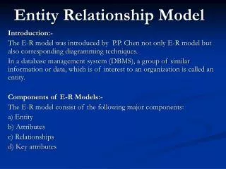
Summary of Conceptual Design • Conceptual designfollows requirements analysis, • Yields a high-level description of data to be stored • ER model popular for conceptual design • Constructs are expressive, close to the way people think about their applications. • Note: There are many variations on ER model • Both graphically and conceptually • Basic constructs: entities, relationships, and attributes(of entities and relationships). • Some additional constructs: weak entities, ISA hierarchies, and aggregation.
Summary of ER (Cont.) • Several kinds of integrity constraints: • key constraints • participationconstraints • overlap/coveringfor ISA hierarchies. • Some foreign key constraintsare also implicit in the definition of a relationship set. • Many other constraints (notably, functional dependencies) cannot be expressed. • Constraints play an important role in determining the best database design for an enterprise.
Summary of ER (Cont.) • ER design is subjective. There are often many ways to model a given scenario! • Analyzing alternatives can be tricky, especially for a large enterprise. Common choices include: • Entity vs. attribute, entity vs. relationship, binary or n-ary relationship, whether or not to use ISA hierarchies, aggregation. • Ensuring good database design: resulting relational schema should be analyzed and refined further. • Functional Dependency information and normalization techniques are especially useful.
From ER Model to Relational Model So… how do we convert an ER diagram into a table?? Simple!! Basic Ideas: • Build a table for each entity set • Build a table for each relationship set if necessary (more on this later) • Make a column in the table for each attribute in the entity set • Indivisibility Rule and Ordering Rule • Primary Key
ER to Relational Model • General principles • Entity set => a relation with same attributes • Relationship => a relation whose attributes are keys from participating entity sets + descriptive attributes if any • Special situations • Weak entity sets • Entity Hierarchies (ISA relationships) • Merging relations
Example – Strong Entity Set SID Name PSRN Name Advisor Student Professor Dept Major GPA
Reduction to Relation Schemas • Entity sets and relationship sets can be expressed uniformly as relation schemas that represent the contents of the database. • A database which conforms to an E-R diagram can be represented by a collection of schemas. • For each entity set and relationship set there is a unique schema that is assigned the name of the corresponding entity set or relationship set. • Each schema has a number of columns (generally corresponding to attributes), which have unique names.
name psrn dept Employees Logical DB Design: ER to Relational • Entity sets to tables: CREATE TABLE Employees (psrn INTEGER, name CHAR(20), dept CHAR(12), PRIMARY KEY (ssn))
Representing Entity Sets With Simple Attributes • A strong entity set reduces to a schema with the same attributesstudent(ID, name, tot_cred) • A weak entity set becomes a table that includes a column for the primary key of the identifying strong entity set section ( course_id, sec_id, sem, year )
Representation of Weak Entity Set • Weak Entity Set Cannot exists alone • To build a table/schema for weak entity set • Construct a table with one column for each attribute in the weak entity set • Remember to include discriminator • Augment one extra column on the right side of the table, put in there the primary key of the Strong Entity Set (the entity set that the weak entity set is depending on) • Primary Key of the weak entity set = Discriminator + foreign key
Representation of Relationship Set --This is a little more complicated-- • Unary/Binary Relationship set • Depends on the cardinality and participation of the relationship • Two possible approaches • N-ary (multiple) Relationship set • Primary Key Issue • Identifying Relationship • No relational model representation necessary
Representing Relationship SetUnary/Binary Relationship • For one-to-one relationship w/out total participation • Build a table with two columns, one column for each participating entity set’s primary key. Add successive columns, one for each descriptive attributes of the relationship set (if any). • For one-to-one relationship with one entity set having total participation • Augment one extra column on the right side of the table of the entity set with total participation, put in there the primary key of the entity set without complete participation as per to the relationship.
Example – One-to-One Relationship Set Degree SID Name ID Code Student study Major Major GPA * Primary key can be either SID or Maj_ID_Co
Example – One-to-One Relationship Set Condition SID Name 1:1 Relationship S/N # Student Have Laptop Major GPA Brand * Primary key can be either SID or LP_S/N
Representing Relationship SetUnary/Binary Relationship • For one-to-many relationship w/out total participation • Same thing as one-to-one • For one-to-many/many-to-one relationship with one entity set having total participation on “many” side • Augment one extra column on the right side of the table of the entity set on the “many” side, put in there the primary key of the entity set on the “one” side as per to the relationship.
Example – Many-to-One Relationship Set Semester SID Name N:1 Relationship SSN Advisor Student Professor Major GPA Dept Name * Primary key of this table is SID
Representing Relationship SetUnary/Binary Relationship • For many-to-many relationship • Same thing as one-to-one relationship without total participation. • Primary key of this new schema is the union of the foreign keys of both entity sets. • No augmentation approach possible…
Representing Relationship Sets • A many-to-many relationship set is represented as a schema with attributes for the primary keys of the two participating entity sets, and any descriptive attributes of the relationship set. • Example: schema for relationship set advisor advisor = (s_id, i_id)
Redundancy of Schemas • Many-to-one and one-to-many relationship sets that are total on the many-side can be represented by adding an extra attribute to the “many” side, containing the primary key of the “one” side • Example: Instead of creating a schema for relationship set inst_dept, add an attribute dept_name to the schema arising from entity set instructor
Redundancy of Schemas For one-to-one relationship sets, either side can be chosen to act as the “many” side That is, extra attribute can be added to either of the tables corresponding to the two entity sets If participation is partial on the “many” side, replacing a schema by an extra attribute in the schema corresponding to the “many” side could result in null values The schema corresponding to a relationship set linking a weak entity set to its identifying strong entity set is redundant. Example: The section schema already contains the attributes that would appear in the sec_course schema
Composite and Multivalued Attributes Composite attributes are flattened out by creating a separate attribute for each component attribute Example: given entity set instructor with composite attribute name with component attributes first_name and last_name the schema corresponding to the entity set has two attributes name_first_name and name_last_name Prefix omitted if there is no ambiguity Ignoring multivalued attributes, extended instructor schema is instructor(ID, first_name, middle_initial, last_name,street_number, street_name, apt_number, city, state, zip_code, date_of_birth)
Composite and Multivalued Attributes A multivalued attribute M of an entity E is represented by a separate schema EM Schema EM has attributes corresponding to the primary key of E and an attribute corresponding to multivalued attribute M Example: Multivalued attribute phone_number of instructor is represented by a schema:inst_phone= (ID, phone_number) Each value of the multivalued attribute maps to a separate tuple of the relation on schema EM For example, an instructor entity with primary key 22222 and phone numbers 456-7890 and 123-4567 maps to two tuples: (22222, 456-7890) and (22222, 123-4567)
Representing Composite Attribute • Relational Model Indivisibility Rule Applies • One column for each component attribute • NO column for the composite attribute itself SSN Name Professor Address Street City
Representing Multivalue Attribute • For each multivalue attribute in an entity set/relationship set • Build a new relation schema with two columns • One column for the primary keys of the entity set/relationship set that has the multivalue attribute • Another column for the multivalue attributes. Each cell of this column holds only one value. So each value is represented as an unique tuple • Primary key for this schema is the union of all attributes
Example – Multivalue attribute The primary key for this table is Student_SID + Children, the union of all attributes SID Name Children Student Major GPA
Multivalued Attributes (Cont.) Special case:entity time_slot has only one attribute other than the primary-key attribute, and that attribute is multivalued Optimization: Don’t create the relation corresponding to the entity, just create the one corresponding to the multivalued attribute time_slot(time_slot_id, day, start_time, end_time) Caveat: time_slot attribute of section (from sec_time_slot) cannot be a foreign key due to this optimization
Design Issues Use of entity sets vs. attributes Use of phone as an entity allows extra information about phone numbers (plus multiple phone numbers)
Design Issues Use of entity sets vs. relationship setsPossible guideline is to designate a relationship set to describe an action that occurs between entities
Design Issues Binary versus n-ary relationship setsAlthough it is possible to replace any nonbinary (n-ary, for n > 2) relationship set by a number of distinct binary relationship sets, a n-ary relationship set shows more clearly that several entities participate in a single relationship. Placement of relationship attributes e.g., attribute date as attribute of advisor or as attribute of student
Representing Relationship SetN-ary Relationship • Intuitively Simple • Build a new table with as many columns as there are attributes for the union of the primary keys of all participating entity sets. • Augment additional columns for descriptive attributes of the relationship set (if necessary) • The primary key of this table is the union of all primary keys of entity sets that are on “many” side • That is it, we are done.
Example – N-ary Relationship Set P-Key1 D-Attribute A-Key E-Set 1 P-Key2 A relationship Another Set E-Set 2 P-Key3 E-Set 3 * Primary key of this table is P-Key1 + P-Key2 + P-Key3
Relationship Example since name dname psrn budget dob did Works_In Employees Departments
Relationship Sets to Tables • In translating a relationship set to a relation, attributes of the relation must include: • Keys for each participating entity set (as foreign keys). • All descriptive attributes. CREATE TABLE Works_In( psrn INTEGER, did INTEGER, since DATE, PRIMARY KEY (psrn, did), FOREIGN KEY (psrn) REFERENCES Employees, FOREIGN KEY (did) REFERENCES Departments)
Weak Entities • A weak entitycan be identified uniquely only by considering the primary key of another (owner) entity. • Owner entity set and weak entity set must participate in a one-to-many relationship set (one owner, many weak entities). • Weak entity set must have total participation in this identifying relationship set. name cost pname age psrn dept Policy Dependents Employees
Translating Weak Entity Sets • Weak entity set and identifying relationship set are translated into a single table. • When the owner entity is deleted, all owned weak entities must also be deleted. CREATE TABLE Dep_Policy ( pname CHAR(20), age INTEGER, cost REAL, psrn INTEGER NOT NULL, PRIMARY KEY (pname, ssn), FOREIGN KEY (psrn) REFERENCES Employees, ON DELETE CASCADE)
since name dname ssn lot Employees Manages Review: Key Constraints • Each dept has at most one manager, according to the key constrainton Manages. budget did Departments Translation to relational model? 1-to-1 1-to Many Many-to-1 Many-to-Many
Translating ER Diagrams with Key Constraints CREATE TABLE Manages( ssn CHAR(11), did INTEGER, since DATE, PRIMARY KEY (did), FOREIGN KEY (ssn) REFERENCES Employees, FOREIGN KEY (did) REFERENCES Departments) • Map relationship to a table: • Note that did is the key now! • Separate tables for Employees and Departments. • Since each department has a unique manager, we could instead combine Manages and Departments. CREATE TABLE Dept_Mgr( did INTEGER, dname CHAR(20), budget REAL, ssn CHAR(11), since DATE, PRIMARY KEY (did), FOREIGN KEY (ssn) REFERENCES Employees)
Review: Participation Constraints • Does every department have a manager? • If so, this is a participation constraint: the participation of Departments in Manages is said to be total (vs. partial). CREATE TABLE Dept_Mgr( did INTEGER, dname CHAR(20), budget REAL, ssn CHAR(11) NOT NULL, since DATE, PRIMARY KEY (did), FOREIGN KEY (ssn) REFERENCES Employees, ON DELETE NO ACTION)
Redundancy of Schemas • Many-to-one and one-to-many relationship sets that are total on the many-side can be represented by adding an extra attribute to the “many” side, containing the primary key of the “one” side • Example: Instead of creating a schema for relationship set account_branch, add an attribute branch_name to the schema arising from entity set account
Review: ISA Hierarchies • If we declare A ISA B, every A entity is also considered to be a B entity. name ssn lot • Overlap constraints: Can Joe be an Hourly_Emps as well as a Contract_Emps entity? (Allowed/disallowed) • Covering constraints: Does every Employees entity also have to be an Hourly_Emps or a Contract_Emps entity? (Yes/no) Employees hours_worked hourly_wages ISA contractid Contract_Emps Hourly_Emps
Translating ISA Hierarchies to Relations • General approach: • 3 relations: Employees, Hourly_Emps and Contract_Emps. • Hourly_Emps: Every employee is recorded in Employees. For hourly emps, extra info recorded in Hourly_Emps (hourly_wages, hours_worked, ssn); must delete Hourly_Emps tuple if referenced Employees tuple is deleted). • Queries involving all employees easy, those involving just Hourly_Emps require a join to get some attributes. • Alternative: Just Hourly_Emps and Contract_Emps. • Hourly_Emps: ssn, name, lot, hourly_wages, hours_worked. • Each employee must be in one of these two subclasses.
Representing Class Hierarchy • Two general approaches depending on disjointness and completeness • For non-disjoint and/or non-complete class hierarchy: • create a table for each super class entity set according to normal entity set translation method. • Create a table for each subclass entity set with a column for each of the attributes of that entity set plus one for each attributes of the primary key of the super class entity set • This primary key from super class entity set is also used as the primary key for this new table
Example SSN Name Person SID Status Gender ISA Student Major GPA
Representing Class Hierarchy • Two general approaches depending on disjointness and completeness • For disjoint AND complete mapping class hierarchy: • DO NOT create a table for the super class entity set • Create a table for each subclass entity set include all attributes of that subclass entity set and attributes of the superclass entity set • Simple and Intuitive enough, need example?
SSN Name Example No table created for superclass entity set SJSU people ISA SID Student Faculty Disjoint and Complete mapping Major Dept GPA
name ssn lot Employees Policies policyid cost name ssn lot Employees Beneficiary Policies policyid cost Binary vs. Ternary Relationships pname age • If each policy is owned by just 1 employee, and each dependent is tied to the covering policy, first diagram is inaccurate. • What are the additional constraints in the 2nd diagram? Dependents Covers Bad design pname age Dependents Purchaser Better design
Binary vs. Ternary Relationships CREATE TABLE Policies ( policyid INTEGER, cost REAL, ssn CHAR(11) NOT NULL, PRIMARY KEY (policyid). FOREIGN KEY (ssn) REFERENCES Employees, ON DELETE CASCADE) • The key constraints allow us to combine Purchaser with Policies and Beneficiary with Dependents. • Participation constraints lead to NOT NULLconstraints. CREATE TABLE Dependents( pname CHAR(20), age INTEGER, policyid INTEGER, PRIMARY KEY (pname, policyid). FOREIGN KEY (policyid) REFERENCES Policies, ON DELETE CASCADE)
Binary Vs. Non-Binary Relationships Some relationships that appear to be non-binary may be better represented using binary relationships E.g., A ternary relationship parents, relating a child to his/her father and mother, is best replaced by two binary relationships, father and mother Using two binary relationships allows partial information (e.g., only mother being know) But there are some relationships that are naturally non-binary Example: proj_guide
Converting Non-Binary Relationships to Binary Form In general, any non-binary relationship can be represented using binary relationships by creating an artificial entity set. Replace R between entity sets A, B and Cby an entity set E, and three relationship sets: 1. RA, relating E and A 2. RB, relating E and B 3. RC, relating E and C Create a special identifying attribute for E Add any attributes of R to E For each relationship (ai , bi , ci) in R, create 1. a new entity eiin the entity set E 2. add (ei , ai ) to RA 3. add (ei , bi) to RB 4. add (ei , ci ) to RC