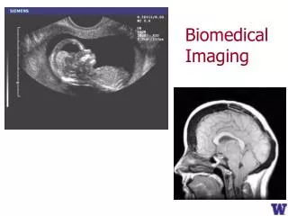
Biomedical Imaging 2
Biomedical Imaging 2. Class 4 – Optical Coherence Tomography (OCT) 02/19/08. Optical biopsy – definition . The in situ imaging of tissue microstructure with a resolution approaching that of histology, but without the need for tissue excision and processing

Biomedical Imaging 2
E N D
Presentation Transcript
Biomedical Imaging 2 Class 4 – Optical Coherence Tomography (OCT) 02/19/08
Optical biopsy – definition • The in situ imaging of tissue microstructure with a resolution approaching that of histology, but without the need for tissue excision and processing • A ballistic optical imaging modality • Analogous to ultrasonography
Optical coherence tomography • Three-dimensional imaging technique with ultrahigh spatial resolution, even in highly scattering media • Based on measurements of the reflected light from tissue discontinuities • e.g., the epidermis-dermis junction • i.e., principal contrast mechanism is the tissue scattering coefficient μs • To a lesser extent, polarization is a contrast mechanism • Based on interferometry • involves interference between the reflected light and the reference beam.
Components of NIR Propagation in Tissue • Light propagation (Monte Carlo simulation) Absorption “Snake” component Incident light Ballistic component Diffuse reflectance Diffuse transmittance Courtesy of Prof. P.E. Andersen, Risø, Technical University of Denmark
E = ER + ES Concept of Interferometry
The OCTsetup Fiber-optic beamsplitter Broadband source Tissue Scanning reference mirror Detector Computer Amplifier Bandpass filter Courtesy of Prof. P.E. Andersen, Risø, Technical University of Denmark
Reference mirror Tissue How To Achieve a Depth Profile
Source spectrum and envelope Courtesy of Prof. P.E. Andersen, Risø, Technical University of Denmark
Resolution (log) 1 mm Ultrasound 100 mm 10 mm Confocalmicroscopy 1 mm Penetration depth (log) 1 mm 1 cm 10 cm OCT vs. standard imaging Standardclinical Highfrequency OCT Courtesy of Prof. P.E. Andersen, Risø, Technical University of Denmark
Construction of image Courtesy of Prof. P.E. Andersen, Risø, Technical University of Denmark
Choosing the light source • Four primary considerations • wavelength, • bandwidth, • power (in a single-transverse-mode), • stability; • portability, ease-of-use, etc. Courtesy of Prof. P.E. Andersen, Risø, Technical University of Denmark
Choose light source – wavelength Courtesy of Prof. P.E. Andersen, Risø, Technical University of Denmark
Choose light source – wavelength Courtesy of Prof. P.E. Andersen, Risø, Technical University of Denmark
Lateral resolution (2/2) Courtesy of Prof. P.E. Andersen, Risø, Technical University of Denmark
Light propagation in sample • The sample • need to describe light-tissue interaction taking temporal and spatial coherence properties into account; • can transport theory be used? • Light-tissue interaction may be modelled by using, for example, the extended Huygens-Fresnel principle • correlation between tissue, state of tissue (lesions) and optical properties? Courtesy of Prof. P.E. Andersen, Risø, Technical University of Denmark
Schematic of fitting algorithm D. Levitz et al., Opt. Express 12, 249-259 (2004) Courtesy of Prof. P.E. Andersen, Risø, Technical University of Denmark
Analytical OCT model • Mean square heterodyne signal current – general expression • μs scattering coefficient • w spot size (H,absence, & S, presence of scattering) • beffective backscattering cross section • P optical power (R: reference; S: sample) • a conversion from optical power to current • heterodyne efficiency factor Courtesy of Prof. P.E. Andersen, Risø, Technical University of Denmark
Ophthalmology diagnosing retinal diseases. Dermatology skin diseases, early detection of skin cancers. Cardio-vascular diseases vulnerable plaque detection. Endoscopy (fiber-optic devices) gastrology, … Functional imaging Doppler OCT, spectroscopic OCT, optical properties, PS-OCT. OCT in non-invasive diagnostics • Guided surgery • delicate procedures • brain surgery, • knee surgery, • … Courtesy of Prof. P.E. Andersen, Risø, Technical University of Denmark
Commercial systems • Ophthalmology • Humphrey (division of Zeiss), US; • www.humphrey.com, • Ophthalmic Technologies Inc., Can. • … • Cardio-vascular diseases • Lightlab Imaging, US; • www.lightlabimaging.com. • Dermatology • Isis Optronics, D; • www.isis-optronics.de, • OCT Innovation, Den, • … Courtesy of Prof. P.E. Andersen, Risø, Technical University of Denmark
Applications:Ophthalmology Humphrey® Optical Coherence Tomography scanner at Herlev Hospital. Courtesy of Prof. P.E. Andersen, Risø, Technical University of Denmark
Applications:Ophthalmology Courtesy of Prof. P.E. Andersen, Risø, Technical University of Denmark
Applications: Ophthalmology Department of Ophthalmology, The New York Eye & Ear Infirmary, New York, NY 10003, USA Courtesy of Prof. P.E. Andersen, Risø, Technical University of Denmark
Normal Eye 250 microns Humphrey Nominal width of scan: 2.8 mm Courtesy of Prof. P.E. Andersen, Risø, Technical University of Denmark
UHR-OCT versus commercial OCT W. Drexler et al., “Ultrahigh-resolution ophthalmic optical coherence tomography”, Nature Medicine 7, 502-507 (2001) Courtesy of Prof. P.E. Andersen, Risø, Technical University of Denmark
Applications:Ophthalmology • Assessment of treatment (choroid) Courtesy of Prof. P.E. Andersen, Risø, Technical University of Denmark
Clinically adapted systems Courtesy of Prof. P.E. Andersen, Risø, Technical University of Denmark
Applications: Dermatology • Dermatology • Medical Laser Center Lübeck GmbH, Lübeck, Germany. sub-epidermal blister (in vivo) at the forearm (3 by 1.5 mm2) sub-dermal blister (in vivo) at the forearm (2 by 1.5 mm2) Courtesy of Prof. P.E. Andersen, Risø, Technical University of Denmark
Applications: Dermatology Courtesy of Prof. P.E. Andersen, Risø, Technical University of Denmark
Applications: Dermatology Courtesy of Prof. P.E. Andersen, Risø, Technical University of Denmark
Basics of disease From Essential Pathology, Emanual Rubin & John L. Farber, second edition, J. B. Lippincott Company, 1995, p. 252 Courtesy of Prof. P.E. Andersen, Risø, Technical University of Denmark
Applications: Cardiology • Imaging inside veins OCT Ultrasound Courtesy of Prof. P.E. Andersen, Risø, Technical University of Denmark
OCT vs. histology D. Levitz, L. Thrane, M. H. Frosz, P. E. Andersen, C. B. Andersen, J. Valanciunaite, J. Swartling, S. Andersson-Engels, and P. R. Hansen, Opt. Express 12, 249-259 (2004). Courtesy of Prof. P.E. Andersen, Risø, Technical University of Denmark
Extract scattering coefficient Courtesy of Prof. P.E. Andersen, Risø, Technical University of Denmark
Extract geff Courtesy of Prof. P.E. Andersen, Risø, Technical University of Denmark
In-vitro clinical study – samples • Analysis of the scattering properties at 1300 nm of the human arterial intima • 4 normal, 4 lipid-rich, 3 fibrous, and 3 fibrocalcific aortic segments, • imaged with OCT in Phosphate Buffered Saline, • routine histological processing • intima identified in histology first, then in the corresponding OCT image. • Reference • D. Levitz, L. Thrane, M. H. Frosz, P. E. Andersen, C. B. Andersen, J. Valanciunaite, J. Swartling, S. Andersson-Engels, and P. R. Hansen, Optics Express 12, 249-259 (2004). Courtesy of Prof. P.E. Andersen, Risø, Technical University of Denmark
Image interpretation • OCT images are divided into transverse blocks (~200-300 µm): • normal: 41 • lipid-rich: 40 • fibrous: 34 • fibrocalcific: 36 Courtesy of Prof. P.E. Andersen, Risø, Technical University of Denmark
Application: results Normal arterial blocks 15 – 39 mm-1: 95% Lipid-rich and fibrocalcific arterial blocks < 15 mm-1: 60% Courtesy of Prof. P.E. Andersen, Risø, Technical University of Denmark
Application: results (2) Normal arterial blocks 0.95 - 1: 87.8% Atherosclerotic arterial blocks < 0.95: > 50% Courtesy of Prof. P.E. Andersen, Risø, Technical University of Denmark
OCT: suggested reading • OCT • D. Huang et al., Science 254, 1178 (1991) • A. Fercher, J. Biomed. Optics 1, 157 (1996) • J. M. Schmitt, “Optical coherence tomography (OCT): A review”, IEEE J. Select. Topics Quantum Electron. 5, 1205-1215 (1999) • J. G. Fujimoto et al., “Optical coherence tomography: An emerging technology for biomedical imaging and optical biopsy”, Neoplasia 2, 9-25 (2000) • W. Drexler et al., “Ultrahigh-resolution ophthalmic optical coherence tomography”, Nature Medicine 7, 502-507 (2001) • W. Drexler, “Ultrahigh-resolution optical coherence tomography”, J. Biomed. Opt. 9, 47-74 (2004) Courtesy of Prof. P.E. Andersen, Risø, Technical University of Denmark