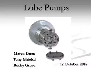
Lobe Pump
Lobe contact is prevented by external timing gears located in the gearbox. Pump shaft support bearings are located in the gearbox, and since the bearings are out of the pumped liquid. As the lobes come out of mesh.

Lobe Pump
E N D
Presentation Transcript
CUSTOMER APPLICATION DATA SHEET NAME: PO. NO: DATE: INVOICE NO: DATE: OPERATING DATA: LIQUID NAME: VISCOSITY: SP. GRAVITY: OPERATING PRESSURE CAPACITY SUCTION PRESSURE OPERATING TEMPRETURE PUMP MODEL PORT SIZE PUMP SPEED DIRECTION OF ROTATION BHP @ PUMP SHAFT MOTOR RATING COUPLING TYPE BARE SHAFT PUMP MOTORISED PUMP SET Authorised by :
INDEX Chapter Page No. 1 General Description 1 2 Installation 2.1 Handling & Storage 2.2 System Design & Installation 2 3 3 Maintenance 3.1 Cleaning in Place (CIP) 3.2 Maintenance Schedule 3.3 Disassembly 3.4 Assembly 4 5 6 9 4 Clearance Chart 13 5 Trouble Shutting 14 6 Part List 16 7 Pumps Speed Selection Chart 17 8 Test & Warrantee Certificate 18
1 GENERAL DESCRIPTION Bare Shaft Pump Lifting hook Geared Motor Lobe Pump Base Frame Pump with drive unit 1
2 Installation 2
2 Installation Discharge Line Pump-1 Pump-2 Suction Line 3
3 Maintenance 4
3 Maintenance 5
3 Maintenance 6
3 Maintenance 7
3 Maintenance 8
3 Maintenance 9
3 Maintenance 10
3 Maintenance Filler Gauge 11
3 Maintenance 12
4 CLEARANCE TABLE Clearance between lobes 4.1 Lobe rotor clearance Table radial clearance Pumps Model Pumps Model ALB 100 S/L ALB 150 S/L ALB 200 S/L ALB 250 S/L ALB 300 S/L ALB 400 S/L 0 0 Between Lobe @ 180 Between Lobe @ 180 0.150 0.150 0.150 0.200 0.300 0.350 Front Front 0.150 0.150 0.150 0.200 0.300 0.350 Rear Rear 0.150 0.150 0.150 0.200 0.300 0.350 Side Side 0.250 0.250 0.250 0.250 0.350 0.400 Rear Front 0.200mm All dimensions are in mm Parralel alignment 4.2 Pump shaft Alignment : Parallel alignment: ± 0.2mm max o ±1 Inclination alignments: ± 1° max Angular alignment 13
5 Trouble Shutting Trouble Shutting Problem Pump stalls when starting Excessive power absorbed Low discharge pressure Prime lost after starting Mechanical seal leakage Packed gland leakage Pump will not prime Pump element wear Noise and vibration Irregular discharge Motor overheats Pump overheats Under capacity No flow Seizure Probable Causes Solutions Reverse motor. Expel gas from suction line and pumping chamber and introduce fluid. Increase suction line diameter. Increase suction head. Simlify suction line configuration and resuce length. Reduce pump speed. Incorrect direction of rotation Pump not Primed. Insufficient NPSH available. Fluid vaporising in suction line. Increase suction line diameter. Increase suction head. Simplify suction line configuration and reduce length. Reduce pump speed. Remake pipework joints. Service fittings. Increase fluid temperature. Decrease pump speed. Check seal face viscosity limitations. Decrease Fluid temperature. Increase pump speed. Cool the pump casing. Reduce fluid temperature. Check seal face and elastomer temp. limitations. Heat the pump casing. Increase fluid temperature. Clean the system. Fit strainer to suction line. Check for obstructions i.e. closed valve. Service system and change to prevent problem recurring. Simplify dicharge line to decrease pressure. Slacken and re-adjust gland packing. adjust gland packing. Decrease pump speed. Increase pump speed. Check alignment of pipes. Fit flexible pipes or expansion fittings. Support pipework. Check alignment and adjust mountings accrdingly. Fit lock washers to slack fasteners and re-tighten. Refer to pump maker for advice and replacement parts. Refer to pump maker's instructions. Check rated and duty presures. Refer to pump maker. Fit new components. Lower pump or raise liquid level. Use optional materials. Air entering suction line. Strainer or filter blocked. Fluid viscosity above rated figure. Fluid viscosity below rated figure. Fluid temp. above rated figure. Fluid temp. below rated figure. Unexpected solids in fuid. Discharge pressure above rated figure Gland over-tightened Gland under-tightened Pump speed above rated figure. Pump speed below rated figure. Pump casing strained by pipework. Flexible coupling misaligned. Insecure pump drive mountings. Shaft bearing wear or failure. Insufficient gearcase lubrication. Metal to metal contact of pumping element. Worn pumping element. Suction lift too high. Fluid pumped not compatible with materials used No barrier system to prevent flow passing. Pump allowed to run dry. Ensure discharge pipework higher than suction tank. Ensure system operation prevents this. Fit single or double flushed mechanical seals. Fit flushed packed gland. Check and replace motor bearings. Fit pumping element. Faulty motor. Pumping element missing 14
26 29 27 28 30 31 23 25 24 32 41 39 19 40 33 37 34 38 15 8 9 12 35 10 22 14 21 36 11 20 15 18 13 16 17 4 3 7 2 6 1 5
6 Parts list 1. 2. 3. 4. 5. 6. 7. 8. 9. 10. 11. 12. 13. 14. 15. 16. nut, front cover front cover O'Ring, Front cover stud hex cap nut O'Ring for lobe sealing lobe nut, pump casing washer dowel stud, pump casing shims pump casing bolt, clamp plate seal clamp plate mechanical seal, stationary parts mechanical seal, rotary parts seal spacer drain bolt, bearing cover 21. 22. 23. 24. 25. 26. 27. 28. 29. 30. 31. 32. 33. 34. 35. 36. 37. 38. 39. 40. 41. Bearing cover oil seal bearing cover bolt, back cover back cover oil seal, back cover bolt, clamp plate clamp plate locking ring outer locking ring inner timing gear ring nut, bearing lock bearings, rear bearing spacer bearings, front stator shaft rotor shaft gear casing oil inlet oil indicator blot, base base 17. 18. 19. 20. 16
7 Pump Speed Selection Chart * Speed of the pump should not exceed from the chart * Pump operating speed depends upon liquid viscosity pump speed chart pump operating speed (rpm) liquid viscosity (cst) 1000 upto 1500 750 1500 - 5000 500 5000 - 15000 380 15000 - 30000 300 30000 - 50000 200 50000 - 100000 150 100000 - 200000 17
8 TEST & WARRANTEE CERTIFICATE TEST RESULT MODEL : RATED PRESSURE PUMP NO : RATED CAPACITY TEST DURATION : TEST TEMP. TEST MEDIA KGF/CM2 LPM PRESSURE CAPACITY POWER CONSUMED SPEED HP RPM Signature : QC DEPARTMENT 18
Other Products ANI ENGINEERS Plot no. 2716, G.I.D.C. Estate, Phase-IV, Wadhwan 363 035. Surendranagar (Guj.) India. Ph.: +91-2752-241479, Fax : +91-2752-242479 Web : www.anivaryapumps.com, E-mail : mail@anivaryapumps.com