Download
1 / 42
420 likes | 587 Views
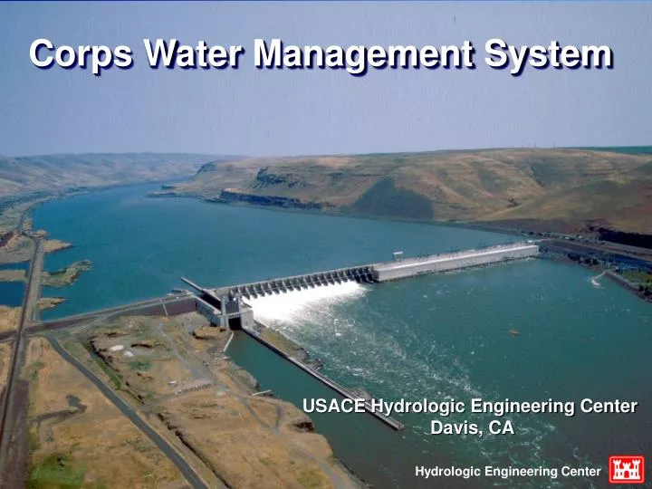
Hydrologic Engineering Center. Corps Water Management System. USACE Hydrologic Engineering Center Davis, CA. Objectives. Overview and Concept of CWMS Scope for ACF Basin CWMS Deployment ACT/ACF Emergency Action Plan. Water Control Mission. Real-Time Decision Support for Water Management

E N D
Hydrologic Engineering Center Corps Water Management System USACE Hydrologic Engineering Center Davis, CA
Objectives • Overview and Concept of CWMS • Scope for ACF Basin CWMS Deployment • ACT/ACF Emergency Action Plan
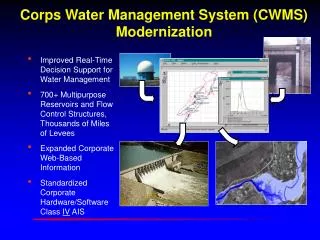
Water Control Mission • Real-Time Decision Support for Water Management • 700+ Multipurpose Reservoirs and Flow Control Structures, Thousands of Miles of Levees • Expanded Corporate Web-Based Information
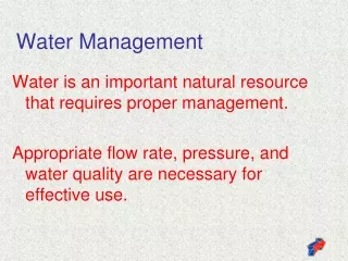
CWMS An integrated system of hardware, software, and communication resources supporting Corps’ real-time water control mission
History 2009 Harris systems gone, PCs, workstations take over mainframe functions, some real-time modeling, and data handling, corporate WCDS modernization plan evolves and work on modernized system begins Manual data collection, storage, analysis, interpretation, modeling historic data begins CWMS deployed Corps-wide development of forecast models for all major watersheds. 1975 1985 1995 2000 Automated data systems, satellite broadcast of data, modeling tools develop, deployment of Harris computer systems. CWMS integrated suite of hydrologic, operations and impact analysis models available,
CWMS Software Integrates the Processing from Data to Water Management Decisions SERVERS Weather Forecast Data Processing Data Storage Modeling Observed Data Public and Cooperators Field Office Instructions Water Control Management Decisions
CWMS - Major Components • Database • Stores hydromet data in Oracle DBMS • Manages retrieval and display of same • Data Acquisition (Observations) • Collects real-time data from data streams • Decodes, validates, and transforms the raw data • Modeling (Forecasts) • Manages model configurations for watersheds • Runs models for operational forecasts
CWMS Components Data Collection Data Base Modeling Data Visualization Information dissemination
Data Acquisition • Collect: • Static data: physical data for model development • Real-time data: observed stream flow, precipitation, temperature, water quality, gate settings, reservoir levels, etc. • Decode • Validate • Transform
Model Results Time of Forecast Time of Forecast
Real-Time Simulation Modeling for Decision Support I see a hurricane in your future.
Modeling (Hydrology) (Storage) HMS ResSim RAS FIA (Damages) (Hydraulics) Watershed Modeling Data Collection Data Base Modeling Data Visualization Information dissemination
The Modeling Process 1) Check status & currency of real-time data 2) Select a forecast time 3) Adjust model parameters 4) Perform model computations 5) View results 6) Modify model parameters as necessary 7) Re-compute simulation
Precipitation Analysis • Precipitation processed on a grid basis. • Observed data from NEXRAD or interpolated from gages. • Future Precipitation Scenarios: • NWS Quantitative Precipitation Forecasts (QPF) • Multiples of the QPF • Manual-entry or standard scenarios (What if?) • Timing • Location (watershed “zones”)
HEC-ResSimReservoir Simulation System Simulates reservoir regulation using inflow hydrographs & project characteristics
River Hydraulics HEC-RAS • Analyzes river hydraulics to compute water depth, velocity, & inundation boundaries • Computes water surface profiles and stage hydrographs from HEC-ResSim hydrographs • Steady-flow or unsteady-flow analysis. • Channel friction adjusted through CWMS interface • Used in conjunction with Arc, inundation boundaries and depth maps are computed then viewed with CorpsView, an extension to Arc
Economic / Impact Analysis (HEC-FIA) • Computes agricultural and urban damages and project benefits by “impact area” • Computes damages and benefits between different scenarios, and with and without project conditions • “Action tables” provide a list and time of actions to take during an event, based on forecasted stages
HEC-HMS computes forecasted flows from Observed precipitation from NEXRAD and rain gages Future precipitation forecasts and scenarios Observed flow ResSim simulates reservoir operations and downstream flows from HEC-HMS flows. HEC-RAS computes stages and inundation areas from ResSim flows. FIA computes damages and impacts from HEC-RAS stages or ResSim flows. Inundation areas and depths are displayed in CorpsView, an extension to ARC. CWMSModel Linking
CWMS Summary • Comprehensive, integrated system for real-time water control decision support • Complete data retrieval / verification / database system • Full range of hydrologic / hydraulic modeling software to evaluate operational decisions and compare the impact of various “what if?” scenarios • Client / Server architecture, with full set of visualization tools to evaluate data and model results
Corps Water Management System CWMS Deployment at ACF Basin
ACF Basin CWMS Deployment • The ACF basin is selected in the SAD region. • Funded by the U.S. Army Corps of Engineers’ Hydrologic Engineering Center (HEC) • Being conducted by WEST Consultants, Inc., HEC’s BPA contractor • Timeline: October 2009 – September 2010
Major Tasks • HEC-HMS rainfall-runoff simulation • For the entire watershed • Use information from existing hydrologic models as much as possible • Based on gridded precipitation • Extensive model calibration/validation
Major Tasks • HEC-ResSim reservoir simulation • Hourly time-step • Including all Corps’ and GPC projects • Convert from the daily model currently being developed by the SAM and HEC • Inflow to HEC-ResSim comes from HEC-HMS and/or NWS • Output from the NWS model will be saved as HEC-DSS files and automatically uploaded to the SAM CWMS database
Major Tasks • HEC-RAS Unsteady Flow Simulation • One-dimensional unsteady flow model • The geometry is georeferenced • Inflow to HEC-RAS comes from HEC-HMS/HEC-ResSim and/or NWS/USGS • Extensive model calibration/validation
Major Tasks • HEC-RAS Unsteady Flow Simulation • Three reaches • Chattahoochee River from Lake Lanier to Norcross (approximately 20 miles) • Chattahoochee River from West Point to Langdale Dam (approximately 7 to 9 miles) • Apalachicola River from Jim Woodruff Dam to Apalachicola Bay
Major Tasks • HEC-RAS Unsteady Flow Simulation • Inundation mapping is not part of this CWMS deployment effort. • It can be done using the CWMS model results since the HEC-RAS models are georeferenced.
Major Tasks • HEC-FIA Flood Impact Analysis • Compute flood damage and benefit • Two reaches • Chattahoochee River from Lake Lanier to Norcross (approximately 20 miles) • Chattahoochee River from West Point to Langdale Dam (approximately 7 to 9 miles)
Major Tasks • CWMS Integration • Link all model components together • Test the CWMS system for selected events • Stress test for real-time operational forecast
ACT/ACF Emergency Action Plan • Dam failure analysis • Inundation Mapping Support • Stimulus Funded
Purpose • Documents actions to be taken by project personnel should a distress indicator be identified • Emergency Notification Plan which identifies the notification procedures for rapid dissemination of emergency actions • Time available for corrective action is most critical • Instantaneous failure – few minutes to 2 days • Time of travel of flood wave from origin to areas
What’s required?– Dam Break Analysis • Time available for corrective action is most critical • Instantaneous failure – few minutes to 2 days • Time of travel of flood wave from origin to areas downstream • Inundation maps which indicate the areas which would be flooded as a result of a hypothesized dam failure
ACT Allatoona Carters ACF Buford West Point Projects
Products • HEC-GeoRAS and HEC-RAS models to simulate the flows from the tributary areas and from the dam in a breached and non-breached condition • Spillway design discharge, without dam failure • Spillway design discharge, with dam failure • Dam failure at normal high pool level • Discharge at normal high pool, without dam failure
Analysis • The A/E will apply the models and route the resulting flows downstream to a point where there is less than a 2 foot increase in stage between the dam failure and non failure cases • No bridge or culvert data will be used in developing the HEC-RAS model. It is assumed that the effects of a dam or culvert would be minor in comparison to the magnitude of the flows resulting from dam failure. • Summary tables of peak flows, stages, flood wave arrival time, and velocities by station
Data Collection • To perform the dam failure analyses and inundation mapping • Available 10m DEMs from the USGS National Elevation Dataset • Current Water Control Manuals (WCM)