Carburetion in SI Engines: Process, Factors & Optimization
780 likes | 808 Views
Explore the theory, types of carburettors, electronic fuel injection, stages of combustion, fuel rating, and factors affecting carburetion in SI engines. Learn about the mixture requirements at variable loads and speeds.

Carburetion in SI Engines: Process, Factors & Optimization
E N D
Presentation Transcript
Content (1) Theory of Carburetion, Types of Carburettors, (No-Numerical on Carburetion) (2) Electronic fuel injection system, Gasoline direct injection (GDI), MPFI System. (3) Combustion in SI engines, stages of combustion, flame propagation, rate of pressure rise, abnormal combustion, Phenomenon of Detonation in S.l. engines, effect of engine variables on detonation. Combustion chambers. (4) Rating of fuels in SI. engines, Additives Prof. Yogesh Sonawane(9975708447)
Carburetion • The SI engines use usually the volatile fuels e.g. petrol, alcohol, etc. • The mixture of fuel and air is prepared outside the engine cylinder and partly evaporated mixture is supplied to the engine. • The mixture prepared outside the cylinder is never homogeneous. Droplets of fuel continue to evaporate even during the suction and exhaust strokes. • Therefore the process of formation of mixture is very important for SI for the engine to operate efficiently under all operating conditions. Prof. Yogesh Sonawane(9975708447)
Carburetion • The process of preparation of mixture of atomized fuel and air before entering to the cylinder is called carburetion. • The device which supplies the metered spray of fuel mixed with correct amount of air for efficient combustion in cylinder at all operating conditions is called carburettor. Prof. Yogesh Sonawane(9975708447)
InductionSystem (Fuel Feeding) for S.I. Engines Prof. Yogesh Sonawane(9975708447)
Induction System (Fuel Feeding) for S.I. Engines • Induction System is to supply partly vaporized mixture of fuel and air to various cylinders of the engine. • It consists of supply of fuel from fuel tank and air from surroundings to carburettor in which the fuel is partially evaporated (atomised). • The partly evaporated fuel and air mixture from carburettor is carried through a pipe line, called intake manifolds, to the engine cylinder. Prof. Yogesh Sonawane(9975708447)
Factors Affecting Carburetion (1) Speed: • The time available for formation of mixture by the carburettor is greatly affected by the speed of the engine. • If an engine runs at 5000 rpm, the time available for the process of carburetion is in the range of 0.0075 to 0.01 seconds. • In such a short period, the fuel is required to be atomised, mixed with air, vaporized and to be inducted into the engine cylinder. • So, the design of a carburettor becomes important to accomplish the above processes in such a short period, particularly, with regard to design of its venturi. Prof. Yogesh Sonawane(9975708447)
Factors Affecting Carburetion (2) Temperature of inlet air: • Higher the surrounding air temperature, higher the vaporization of fuel and homogeneity of mixture. • However increased temperatures reduce the volumetric efficiency, hence, the power output. (3) Volatility of fuel: • Complete vaporization could be achieved by using highly volatile fuels, which are expensive to produce, or by using heat in intake manifolds to promote vaporization. Prof. Yogesh Sonawane(9975708447)
Factors Affecting Carburetion • However, excessive vaporization of fuel decreases the efficiency and reduces the power output of the engine. (4) Design of intake manifolds: • When the multicylinder engines receive a partially vaporized mixture of fuel and air, each cylinder does not receive the same amount of fuel. • Therefore, the design of intake manifolds becomes essential to ensure proper distribution of fuel. Prof. Yogesh Sonawane(9975708447)
Mixture Requirements: • Petrol fuel used in SI engine is mainly octane (C8 H18) for which the chemically correct or stoichiometric mixture of air-fuel ratio is 15.12 : 1 by mass approximately. This mixture gives most rapid combustion of fuel, almost the great power and reasonable economy of fuel. • Rich mixtures give more power in the ratio of 11: 1 to 15: 1 of air and fuel and or lean mixtures of about 16 to 18 : 1 gives better fuel economy. • Rich mixtures having A.F. ratio below 11: 1 and lean mixtures above 20: 1 cannot burnt effectively. Prof. Yogesh Sonawane(9975708447)
Mixture Requirements at Variable Loads and Speeds • The function of carburettor is to form a homogeneous mixture of very fine liquid fuel particles and air in desired proportions (A.F. ratio 11 to 18 : 1), under unsteady conditions such as sudden throttle opening and closing, acceleration and deceleration, at various loads on the engine, starting, idling and initiate maximum power. • The carburettor must provide a different proportion of fuel and air for various conditions of running of the engine. • The various requirements of S I engine are: (a) Maximum power. (b) Minimum specific fuel consumption or maximum economy. (c) Starting, idling and low load running. (d) Acceleration. (e) Part load running range-cruising. Prof. Yogesh Sonawane(9975708447)
Mixture Requirements at Variable Loads and Speeds Fig. Effective throttle opening (%) air-fuel ratio requirements Prof. Yogesh Sonawane(9975708447)
Mixture Requirements at Variable Loads and Speeds • (1) The maximum power:would be obtained if all the oxygen present in the cylinder is utilized. • Practically the mixture of fuel and vapour is never homogeneous and it further diluted by the residual gases. • It is possible that some parts of the oxygen present in the cylinder may not find fuel for burning due to non-homogeneity of mixture though the mixture supplied is chemically correct. • It reduces the power developed by the engine. • Therefore a little rich mixture of r-l ratio 12.5 to 13.5: 1 (approximately) is necessary to ensure that all the oxygen present is fully utilized and such a mixture will give maximum combustion temperatures and power . (Refer Fig.) Fig. Effect of air-fuel ratio on power output and efficiency at full throttle and constant speed Prof. Yogesh Sonawane(9975708447)
Mixture Requirements at Variable Loads and Speeds (2) Maximum Economy of Fuel: • For the maximum economy of fuel consumption it is necessary that all the fuel present in the cylinder is burnt completely. • To ensure the effective burning of fuel it is necessary that a little excess air is required to be supplied to ensure complete combustion. • It is observed that air-fuel ratios in the range of 16.5 to 17.5 1 gives maximum economy of fuel i.e. it gives minimum specific fuel consumption Fig. : Effect of air-fuel ratio on specific fuel consumption at various throttle openings Prof. Yogesh Sonawane(9975708447)
Mixture Requirements at Variable Loads and Speeds (3) Starting, Idling and Low Load Running: • The engine is said to idle when no external load is applied on the engine and at the throttle valve is almost closed. • Under idling conditions the power developed by the engine is just sufficient to overcome the various friction losses of the engine. • Low load running is usually taken in the range of zero to 20% of the rated power the engine. • At the time of starting and idling the engine, the working temperatures are low Therefore, the carburettor is not able to vaporize the fuel and the mixture reaching the cylinder is lean. This may lead to non-initiation of combustion in the cylinder. • To ensure minimum fuel vapour in the cylinder rich mixtures are necessary to initiate the combustion. • Under the conditions of idling and low load running the throttle valve almost closed due to which the pressures in the intake manifolds are much lower than atmospheric pressure while the pressure inside the cylinder is approximately atmospheric pressure at the end of exhaust stroke. • When the inlet valve opens during the suction stroke, there may be back flow of residual gases into the intake manifold. Prof. Yogesh Sonawane(9975708447)
Mixture Requirements at Variable Loads and Speeds • When the piston moves outwards, the residual gases are drawn along with the fresh charge. Therefore the actual mixture inside the cylinder would contain large percentage of residual gases in the fresh charge i.e. the cylinder mixture is too diluted and it is at low temperatures. This diluted mixture is not able to initiate proper combustion. • In order to offset the dilution of fresh charge due to residual gases and low temperatures, it is necessary to supply rich mixtures during starting, idling and low load running of engines. • Usual air-fuel ratio requirements is about 11 to 12: 1 as represented by the curve (a-b) in Fig. Prof. Yogesh Sonawane(9975708447)
Mixture Requirements at Variable Loads and Speeds (4) Acceleration: • Under normal running of engine the fuel that leaves the carburettor is not completely vaporized and a part of the liquid remains in the intake manifolds as liquid film because the liquid particles have larger inertia compared to vaporized fuel. • It does not create any problems under steady state running of engine since the fuel of previous stroke in the intake manifolds vaporizes and supplied to the engine in the subsequent stroke. • When the engine is to be accelerated suddenly by opening the throttle valve, the liquid fuel lags behind in the intake manifolds due to its large inertia. As a result the mixture of fuel and air reaching the cylinder is lean due to instant opening of throttle valve which is contrary to the requirement of rich mixture during acceleration. • In order to compensate this ill effect and to provide the needed rich mixtures during acceleration, a suitable mechanism called acceleration pump is provided in the carburettors. Prof. Yogesh Sonawane(9975708447)
Mixture Requirements at Variable Loads and Speeds (5) Part Load Running - Cruising Range: • Curve (b-c) of shows the part load running of engine which is in the range of 20 to 75% of rated power. • As the load on the engine is increased beyond 20% of load, the throttle valve is opened gradually with the increase in load. It reduces the inlet pressure and the problem of dilution of fresh charge by the residual gases is also reduced. • The air-fuel ratio increases and it ensures economical running of the engine. • Usually air-fuel ratio of about 17 : 1 is kept in cruising range for a single cylinder engine and slightly rich mixtures with air-fuel ratio 16: 1 in case of multicylinder engines. Prof. Yogesh Sonawane(9975708447)
Requirements of a Good Carburettor • To meter the liquid fuel so as to produce the required air-fuel ratios at all operating conditions like during idling, low load running, cruising range and maximum power range. (b) To provide energy to be supplied to change the fuel from liquid to vapour state since the fuel in liquid form or drops will not burn efficiently in an engine. (c) To prepare the homogeneous mixture of fuel and air as far as possible. (d) To provide rich mixtures for ease of starting the engine. (e) To provide the required rich mixture during acceleration. Prof. Yogesh Sonawane(9975708447)
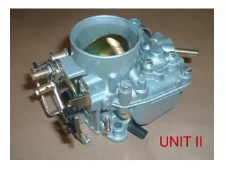
Simple Carburettor Prof. Yogesh Sonawane(9975708447)
Simple Carburettor • It consists of a float in float chamber, venturi and the main fuel jet. • Float chamber is open to atmosphere so pressure in float chamber is atmospheric pressure. • Fuel is supplied to the float chamber through strainer from fuel tank with the help of fuel pump. • The jet tube consists of main nozzle to which fuel is supplied from the float chamber through a main fuel jet. • The suction of the engine draws air through the choke tube and passes through the venturi. Since the area of cross-section at the throat of venturi reduces, the pressure at the main nozzle reduces and the velocity of air increases. • Due to pressure differential caused at the main nozzle and the pressure in the float chamber, the fuel from float chamber is supplied to the main nozzle which mixes with the incoming air. Prof. Yogesh Sonawane(9975708447)
Simple Carburettor • The velocity of air past the venturi vaporizes the petrol fuel partially which is then evaporated by the heat in the intake manifolds and the cylinder walls. • A petrol engine is quantity governed. It means that the amount of charge delivered- is according to power delivered by the engine at a particular speed. This is achieved by a throttle valve of butterfly type. • When the throttle valve opens, more air flows through the venturi tube and more quantity of fuel and air is delivered to the engine, therefore, engine develops more power. • When the throttle valve closes, reverse is the action. Prof. Yogesh Sonawane(9975708447)
Simple Carburettor Nozzle lip (h) • The pressure at the throat under fully open throttle condition lies between 4 to 6 mm of Hg below atmospheric. • In order to avoid overflow of the fuel from nozzle, the main nozzle tip is kept slightly higher than the level of fuel in float chamber. • The difference of level of tip of main nozzle and fuel level in float chamber is called nozzle lip. • If h is the nozzle lip and (Δp)a is the pressure drop due to flow of air, then the pressure drop available for flow of fuel will be, Prof. Yogesh Sonawane(9975708447)
Drawbacks of a simple Carburettor • It provides increasing richness of A/F mixture as the speed of the engine increases because as the throttle valve is opened gradually, the pressure the venturi throat decreases, which decreases density of air with increase in its velocity. Whereas, the quantity of fuel flow remains constant. Therefore, A/F ratio decreases with increase in speed of engine. 2. If the speed is too low, we get very lean mixtures which may not be sufficient ignite the mixture. Prof. Yogesh Sonawane(9975708447)
Modifications of Simple Carburettor Prof. Yogesh Sonawane(9975708447)
Modifications of Simple Carburettor • Starting Choke: • Rich mixture is required at the time of starting of the engine due to cold conditions of the engine. • A butterfly valve called choke is incorporated before the venturi for this purpose. • At the time of cold starting of the engine the choke is almost closed and It lowers the pressure at the venturi. • This large pressure drop between the pressure in the float chamber and at the venturi increases the mass flow rate of fuel thereby ensuring that a very rich mixture is supplied to the engine. Prof. Yogesh Sonawane(9975708447)
Modifications of Simple Carburettor 2) Metering and Idling System • Idling of the engine means no load running of the engine which requires a rich mixture. • At no load, the throttle valve is almost closed and due to this the airflow through the venturi is greatly reduced. • The pressure drop at the venturi is very low and the main jet is not able to supply any fuel. • In order to supply rich mixture an idling circuit is introduced in the carburettor, located below the throttle valve. • The low pressure existing in the intake manifolds past the throttle valve allows the fuel to be supplied from the float chamber through the idle jet thereby enriching the mixture of fuel and air. • The air-fuel mixture discharged into the air stream past the throttle valve is controlled by the idling adjustment screw. • Air bleeds prevent the fuel to be supplied from the float chamber when the engine is shut-off. • At part load running the idle jet becomes ineffective. Prof. Yogesh Sonawane(9975708447)
Modifications of Simple Carburettor Arrangement of Acceleration Condition Prof. Yogesh Sonawane(9975708447)
Modifications of Simple Carburettor (3) Acceleration: • Simple carburettor is not able to supply the required mixture momentarily due to inertia of liquid fuel particles when the engine is to be accelerated by opening the throttle valve suddenly. • To overcome this problem an acceleratingpump is used. • It consists of a piston-cylinder arrangement with a ball valve in the cylinder and a spring. • The piston is forced downwards into cylinder simultaneously when the throttle valve is opened. This forces the extra petrol fuel into the venturi and the amount of fuel is controlled by metering orifice. This way it supplies rich mixture temporarily. The piston is raised again due to the spring force when the throttle valve is again partly closed. Prof. Yogesh Sonawane(9975708447)
Modifications of Simple Carburettor Part load running-metering pin method Prof. Yogesh Sonawane(9975708447)
Modifications of Simple Carburettor (4) Part Load Running-Economic Range (Metering Pin Method) • A simple carburettor supplies rich mixture when the engine speed increases, in the range of 20 to 75% load. • In order to run the engine under maximum economy, a metering pin in the main metering orifice is provided. • The movement of the pin rod in the metering orifice is controlled by a control lever by changing the coefficient of discharge and area of flow of fuel into the main jet. • It controls the supply of fuel flow into the venturi according to the load on the engine. Prof. Yogesh Sonawane(9975708447)
Compensating Devices • A simple carburettor supplies rich mixture with increase in speed. • A carburettor is also required to supply nearly constant A/F ratio over wide range of speed and load for its economic operation. • Air-fuel ratio can be maintained either by increasing the supply of air or by supplying less fuel with increase in speed. • The devices used for maintenance of constant A/F ratio are called compensating devices. Prof. Yogesh Sonawane(9975708447)
Compensating Devices (I) Compensating jet method: Prof. Yogesh Sonawane(9975708447)
Compensating Devices (ii) Auxiliary air valve method: Prof. Yogesh Sonawane(9975708447)
Compensating Devices (iii) Auxiliary port method: Prof. Yogesh Sonawane(9975708447)
Classification of Carburetors • Depending upon working Construction • Constant Choke Carburetor – Choke area is const, • Pressure diff varied by venturieslike Solex, Carter • Constant Vacuum Carburetor – Choke area is varied • and depression/vacuum is kept constant; • SU Carburetor • Depending upon direction of Airflow • Up Draught Carburetor • Down Draught Carburetor • Side/Horizontal/Cross Draught Carburetor
Types of Carburettors: Depending upon the direction of air and fuel flow, the carburettors are classified as: (a) Updraught carburettors (b) Downdraught carburettors (c) Side draught or horizontal carburettors. Prof. Yogesh Sonawane(9975708447)
Analysis of a single jet Carburettor Prof. Yogesh Sonawane(9975708447)
Analysis of a single jet Carburettor Prof. Yogesh Sonawane(9975708447)
Analysis of a single jet Carburettor Prof. Yogesh Sonawane(9975708447)
Analysis of a single jet Carburettor Prof. Yogesh Sonawane(9975708447)
Analysis of a single jet Carburettor Prof. Yogesh Sonawane(9975708447)
Analysis of a single jet Carburettor Prof. Yogesh Sonawane(9975708447)
Analysis of a single jet Carburettor Prof. Yogesh Sonawane(9975708447)
Analysis of a single jet Carburettor Prof. Yogesh Sonawane(9975708447)
Analysis of a single jet Carburettor Prof. Yogesh Sonawane(9975708447)
Analysis of a single jet Carburettor Prof. Yogesh Sonawane(9975708447)
Analysis of a single jet Carburettor Prof. Yogesh Sonawane(9975708447)
Automobile Carburettors: (Solex Carburettor) Prof. Yogesh Sonawane(9975708447)
Automobile Carburettors: (Carter Carburettor) Prof. Yogesh Sonawane(9975708447)