Rapid Prototyping
Rapid Prototyping. Prototype: It is a model fabricated to prove out a concept or an idea. Solid Modelling : It’s a branch of CAD that produces 2D or 3D objects in an electronic format. Definition.

Rapid Prototyping
E N D
Presentation Transcript
Prototype: It is a model fabricated to prove out a concept or an idea. Solid Modelling: It’s a branch of CAD that produces 2D or 3D objects in an electronic format.
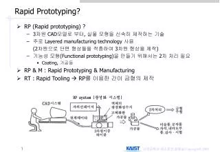
Definition Rapid prototyping is basically a additive manufacturing process used to quickly fabricate a model of a part using 3-D CAM data. It can also be defined as layer by layer fabrication of 3D physical models directly from CAD.
Need for Rapid Prototyping To increase effective communication. To decrease development time. To decrease costly mistakes. To minimise sustaining engineering changes. To extend product life time by adding necessary features & eliminating redundant features early in the design.
Trends in manufacturing industries emphasis the following Increasing the no of variants of products. Increase in product complexity. Decrease in product lifetime before obsolescence. Decrease in delivery time. Product development by Rapid prototyping by enabling better communication.
Conventional Machining Its not suitable for complex shapes because they are difficult to machine. Time consuming Very costly Tedious or very laborious. Skilled operator is required. Accuracy will be less. Increased product development time.
Pre-processing:- CAD model slicing & setting algorithms applied for various RP systems. Post-processing:-Cleaning operations required to finish a part after removing it from RP machine. Materials for Rapid Prototyping: Paper, Wax, Plastics, Resins, Metallic powders.
Methodology of Rapid Prototyping Construct a CAD model. Convert it to STL format. RP machine processes .STL file by creating sliced layers of model. First layer of model is created. Model is then lowered by thickness of next layer. Process is repeated until completion of model
Contd…… The model & any supports are removed. Surface of the model is then finished and cleaned.
History of RapidPrototyping It started in 1980’s First technique is Stereolithography (SLA) It was developed by 3D systems of Valencia in California, USA in 1986. Fused deposition modelling (FDM) developed by stratasys company in 1988.
Laminated object manufacturing (LOM) developed by Helisis (USA). Solid ground Curing developed by Cubitol corporation of Israel. Selective laser sintering developed by DTM of Austin, Texas (USA) in 1989. Sanders Model maker developed by Wilton incorporation USA in 1990. Multi Jet Modelling by 3D systems. 3-D Printing by Solygen incorporation, MIT, USA.
Rapid Prototyping Technologies • Stereolithography (SLA) • Laminated Object Manufacturing(LOM) • Selective Laser Sintering(SLS) • Fused Deposition Modeling(FDM) • Solid Ground Curing(SGC)
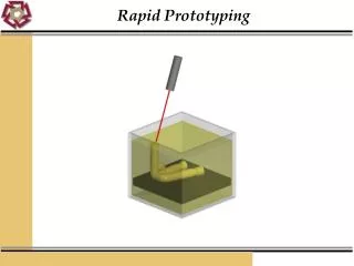
Stereolithography It is the first RP system developed by 3D SYSTEMS of Valencia in California, USA in 1986. First Model developed was 250/50 followed by 250/30, 3500, 5000 and 7000. SLA is a laser based Rapid Prototyping process which builds parts directly from CAD by curing or hardening a photosensitive resin with a relatively low power laser.
Parameters: Laser Type: Helium Cadmium Laser (He-Cd) Laser Power: 24mW Laser Life: 2000 hours Re-coat material: Zaphir Minimum Slice Thickness: 0.1mm Beam Diameter: 0.2mm Scan Speed: 0.75m/sec Maximum Part Volume: 0.25x0.25x0.25 m Maximum Part Weight: 9 kgs
Software SLA CONTROL AND SET UP SOFTWARE: It operates on SLA 250 and SLA 500 machines. It has got three packages. a) SLA VIEW: UNIX based system for viewing and positioning. b) BRIDGE WORKS: UNIX based software for generating support structures.
c) SLA SLICE: Slicing and system operation software. MAESTRO: UNIX based software MS WINDOWS NT SOFTWARE (3D LIGHT YEAR): It is used for viewing, positioning, support generation and slicing, build station for operating SLA machine.
Build Materials Used: • Epoxy Resin, Acrylate Resin • Epoxy Resin has better material properties and less hazardous but require large exposure time for curing.
SLA Hardware A removable VAT that holds the build resin. A detachable perforated build platen on a Z axis elevator frame An automated resin level checking apparatus VAT has a small amount of Z movement capability which allows computer to maintain a exact height per layer.
A recoated blade rides along the track at the top of the rack and serves to smooth the liquid across the part surface to prevent any rounding off edges due to cohesion effects. Some systems have Zaphyrrecoater blade which actually softens up resin and delivers it evenly across the part surface. Behind the build chamber resides the laser and optics required to cure resin.
Laser unit is long rectangular about 4 feet long and remains stationary.
Stereolithography Apparatus Operation The process begins with the solid model in various CAD formats The solid model must consist of enclosed volumes before it is translated form CAD format into .STL FILE The solid model is oriented into the positive octant of Cartesian co-ordinate system and then translate out Z axis by at least 0.25 inches to allow for building of supports
The solid model is also oriented for optimum build which involves placing complex curvatures in XY plane where possible and rotating for least Z height as well as to where least amount of supports are required. The .STL FILE is verified.
The final .STL FILE one which supports in addition to original file are then sliced into horizontal cross sections and saved as slice file. The slice files are then masked to create four separate files that control SLA machine ending with 5 extensions L, R, V and PRM.
Important one is V file. I.e. Vector file. The V file contains actual line data that the laser will follow to cure the shape of the part. R file is the range file which contains data for solid or open fields as well as re-coater blade parameters.
The four build files are downloaded to SLA which begins building supports with platen adjust above the surface level. The first few support layers are actually cured into perforations into platen, thus providing a solid anchor for the rest of the part.
By building, SLA uses laser to scan the cross section and fill across the surface of resin which is cured or hardened into the cross sectional shape. The platen is lowered as the slices are completed so that more resin is available in the upper surface of the part to be cured. Final step is Post Processing.
Post Processing: Ultraviolet Oven (Post Curing Apparatus) An Alcohol Bath. Clean the part in the alcohol bath and then go for final curing.
Advantages: • Parts have best surface quality • High Accuracy • High speed • Finely detailed features like thin vertical walls, sharp corners & tall columns can be fabricated with ease. • Disadvantages: • It requires Post Processing. i.e. Post Curing. • Careful handling of raw materials required. • High cost of Photo Curable Resin.
Applications: • Investment Casting. • Wind Tunnel Modeling. • Tooling. • Injection Mould Tools.
History: • Selective Laser Sintering was developed by university of Texas Austin in 1987. • Selective Laser Sintering Technology: • Selective Laser Sintering is a rapid prototyping process that builds models from a wide variety of materials using an additive fabrication method. • The build media for Selective Laser Sintering comes in powder form which is fused together by a powerful carbon dioxide laser to form the final product.
DTM sinter station 2500 is the machine used for the process. Selective Laser Sintering begins like most other rapid prototyping processes with a standard .STL CAD file format. DTM view software uses the .STL files. This software do the required orientation and scaling of parts.
This machine has auto nesting capabilities which will place multiple part optimally in the build chamber for best processing speed and results. Once the .STL file is placed and parameters are set the model is directly built from the file.
The sinter station has build piston at the center and feed piston on the either side. The model is built layer by layer like other rapid prototyping process so that the build piston will begin at the top of its range and will lower in increments of the set layer size as parts are built.
With the build piston at the top a thin layer of powder is spread across the build area by the roller from one of the feed piston. The laser then cures in a raster sweeps motion across the area of the parts being built.
The part piston lowers and more powder is deposited and the process is continued until all of the part is built. The build media is removed from the machine. It is a cake of powder. This cake is taken to the breakout station where excess powder is removed from the part manually with brushes.
The excess powder that has been removed can be kept for recycling and can be reused. Some material needs additional finishing. Some of the finishing techniques include grid blasting, sanding, polishing, drilling, taping and coating .
Purpose of Selective Laser Sintering: • To provide a prototyping tool • To decrease the time and cost of design to product cycle. • It can use wide variety of materials to accommodate multiple application throughout the manufacturing process.
Applications: 1. As conceptual models. 2. Functional prototypes. 3. As Pattern masters.
Advantages: 1. Wide range of build materials. 2. High throughput capabilities. 3. Self supporting build envelop. 4. Parts are completed faster. 5. Damage is less. 6. Less wastage of material.
Disadvantages: 1. Initial cost of system is high. 2. High operational and maintenance cost. 3. Peripheral and facility requirement.