Download
1 / 25
290 likes | 552 Views
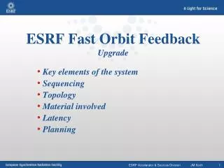
Next Generation Beam Position Acquisition and Feedback Systems ALBA Synchrotron , 12-14 November 2018. A fast orbit correction scheme for the ESRF EBS Eric PLOUVIEZ, Benoit ROCHE, Franck UBERTO ESRF Accelerator & Source Division. Fast Network (DLS CC). 8 Feedback Processors.

E N D
Next Generation Beam Position Acquisition and Feedback Systems ALBA Synchrotron, 12-14 November 2018 A fast orbit correction scheme for the ESRF EBS Eric PLOUVIEZ, Benoit ROCHE, Franck UBERTO ESRF Accelerator & Source Division
Fast Network (DLS CC) 8 Feedback Processors One of the 96 sextupoles housing the steerers Present ESRF fast Orbit Feedback Architecture ----- ----- 7 Liberas In each of the 32 cells Ethernet DLS fast data archiver Group of 7 Libera BPMs per cell 4 cabinets of 18 Power Supplies each 21/10/2019 Page 3 Next Generation Beam Position Acquisition and Feedback Systems, 12-14 November 2018 ESRF Accelerator & Sources Division E. Plouviez JM Koch 2 One of the 224 Beam Position Monitors
MOTIVATION OF OUR APPROACH On our present ring Vertical emittance: 6pm Horizontal emittance: 4nm Orbit stability from .01Hz to 1 Hz: Vertical: .5mm Horizontal: .8mm Orbit stability from 1Hz to 500Hz: Vertical: 1mm Horizontal:1.8mm kickers kickers H rms no FOC 3.5 mm H rms with FOC V rms no FOC V rms with FOC Integrated spectrum of the orbit perturbation with and without fast orbit correction Page 3 Next Generation Beam Position Acquisition and Feedback Systems, 12-14 November 2018
MOTIVATION OF OUR APPROACH • For EBS: • the vertical emittance will be the same and we aim • at reaching the same stability • The horizontal emittance is much lower but the stability • achieved on our present ring would be sufficient • Can we simply reuse our present system without • any extra development? kickers • Which means implementing a fast orbit correction using only: • 6 fast BPM per cell • 3 fast correctors per cell • When the new orbit correction is supposed to require: • 10BPM per cell • 9 correctors per cell Page 4 Next Generation Beam Position Acquisition and Feedback Systems, 12-14 November 2018
NEW FAST ORBIT CORRECTION PERFORMANCE • Stiffer girders: smaller magnets displacement, but at a higher frequency • Stronger quadrupoles fields gradient => Larger kicks for a given magnet motion kickers Eventually, we expect a smaller orbit distortion at high frequency, but maybe a reduced effect of the FOC system due to higher frequencies of the orbit distortions Page 5 Next Generation Beam Position Acquisition and Feedback Systems, 12-14 November 2018
EBS NEW LATTICE 10 BPM per cell: 6 Libera Brillance (with fast ouputs) 4 Libera Sparks (no fast ouputs) 9 correctors per cell: 3 fast correctors (500Hz BW) 6 slow correctors Page 6 Next Generation Beam Position Acquisition and Feedback Systems, 12-14 November 2018
FAST ORBIT CORRECTION PERFORMANCE When the frequency increases, most of the residual distortion will come from the limited bandwidth of the correction kickers Page 7 Next Generation Beam Position Acquisition and Feedback Systems, 12-14 November 2018
FAST ORBIT CORRECTION PERFORMANCE kickers For the BPMs located at he end of the straight section, the correction is nearly perfect Page 8 Next Generation Beam Position Acquisition and Feedback Systems, 12-14 November 2018
Conclusion kickers The 320 BPMs and 288 correctors are required to put the beam optimal orbit in term of coupling, lifetime … However small and fast orbit distortion with no DC component can be corrected with a smaller set of BPM and correctors without spoiling the quality of the correction Page 9 Next Generation Beam Position Acquisition and Feedback Systems, 12-14 November 2018
Scheme Implementation Ethernet link Slow orbit control: Storage ring 96 fast correctors 192 slow correctors 288 X 320 Mcors correction matrix 128 slow BPMs Fast serial link Hybrid slow/fast orbit control flow chart 192 fast BPMs Communication controller network FPGA fast controller: 96 X 192 Mcorf correction matrix PID controller 50Hz notch Offset trim: Slow correctors setting step X Mress
FAST ORBIT CORRECTION COMPONENTS 10kHz data flow From Liberas to the correctors power supplies kickers 48 Power Supplies Crates, each driving 2 correctors Up to 42 corrections 196 X & Z positions 8 FPGA PMCs correctors each driving up to 7 crates (42 channels) Corrections 196 Libera BPMs Diagnostics • Fast data archiver developed by DLS:10days buffer of all the data of the FOC 96 fast correctors Page 11 Next Generation Beam Position Acquisition and Feedback Systems, 12-14 November 2018
CORRECTORS kickers 192 correctors embedded in the sextupoles; Slow response (1Hz BW) 92 fast correctors (500Hz BW capability): Versatile magnets to be used as fast dipoles and skew quadrupole Page 12 Next Generation Beam Position Acquisition and Feedback Systems, 12-14 November 2018
CORRECTORS POWER SUPPLY CONTROL Fast correctors magnets power supplies Each channel receives its setpoint from two sources kickers Dynamic correction: +/- 200mA 16 bits resolution Set point at 10kHz from serial line : FOFB Static correction: +/- 1.8 A maxi 16bits resolution Set point from Ethernet : Golden orbit +2Amp 0 Closed loop resolution: 19 bits or 2ppm -2Amp 96 Steerer number 1 Page 13 Next Generation Beam Position Acquisition and Feedback Systems, 12-14 November 2018
Fast power supply design Fast power supply internal controller: • dI/dt limited => 50Hz bandwith for the full +/- 100mA swing 500Hz small signal bandwidth kickers Dual slow/fast inputs advantage: • By frequently downloading of the average of the fast inputs settings to the slow inputs, the fast stop of the fast correction becomes straightforward… • 19 bits resolution when the loop is closed, without the constraint of a true 19 bits resolution design Page 14 Next Generation Beam Position Acquisition and Feedback Systems, 12-14 November 2018
TEST OF THE EBS FAST ORBIT CORRECTION SCHEME ON THE PRESENT ESRF STORAGE RING We used only 5 BPMs and 2 correctors per cell for the Fast Orbit Correction We used the full set of 7 BPMs and 3 correctors per cell for slow orbit corrections ( one correction every 5 seconds) Page 15 Next Generation Beam Position Acquisition and Feedback Systems, 12-14 November 2018
FAST ORBIT CORRECTION PERFORMANCE kickers Normal correction scheme Mixed slow/fast correction Page 16 Next Generation Beam Position Acquisition and Feedback Systems, 12-14 November 2018
FAST ORBIT CORRECTION PERFORMANCE AT HIGH FREQUENCY kickers H rms no FOC 3.5 mm H rms with FOC V rms no FOC Integrated spectrum of the orbit perturbation with and without fast orbit correction V rms with FOC Page 17 Next Generation Beam Position Acquisition and Feedback Systems, 12-14 November 2018
Effect on the horizontal beam position Perturbation oBservedoN THE HORIZONTAL BEAM POSITION 4 mm 4 mm 1000 turns = 2.8ms 1000 turns Scale for the fast oscillation signal on the right plot due to a BPM bandwidth limitation 3 turns 2.8ms =1turn Blue:kick shape Purple: sextupole effect Next Generation Beam Position Acquisition and Feedback Systems, 12-14 November 2018
Normal Fast Orbit Correction effect: Correction calculated with the normal orbit correction matrix : • Will use mostly two correctors The feedback bandwidth is 150Hz: • The correction will be produced with a delay of about 2ms => no effect! Efficient use of the corrector bandwidth Efficient use of the corrector bandwidth Page 19 Next Generation Beam Position Acquisition and Feedback Systems, 12-14 November 2018
EFFECT OF THE FAST ORBIT CORRECTION ON THE KICK DUE TO THE SEPTUM Orbit Correction Feedback bandwidth: 150Hz Corrector strength: Parasitic kick strength: The correction signal results in overshoot without real reduction of the perturbation peak amplitude. Sometime the orbit correction stops due to an excessive demand on the corrector strength The corrector bandwidth is 500Hz which is enough to generate a correction signal, so how can we use it more efficiently? Page 20 Next Generation Beam Position Acquisition and Feedback Systems, 12-14 November 2018
FEEDFORWARD APPROACH FOR THE FAST ORBIT CORRECTION: Correction signal stored in a look up table : • Efficient use of the corrector bandwidth: • No loop stability problem • Allows some bandwidth extension by pre emphasis of the signal • Better use of the available correction strength: • Correction spread over 6 correctors instead of 2 when the correction is calculated by the feedback loop using the standard SVD derived correction matrix Page 21 Next Generation Beam Position Acquisition and Feedback Systems, 12-14 November 2018
Orbit correction: feedforward correction We can use more correctors : • 6 correctors are available between the two ID straight sections surrounding the injection straight section The correction generation is triggered by the injection timing • no delay • Correction signal generation is fully using the 500Hz correctors bandwidth Efficient use of the corrector bandwidth Efficient use of the corrector bandwidth Page 22 Next Generation Beam Position Acquisition and Feedback Systems, 12-14 November 2018
Orbit correction: feedforward correction Efficient use of the corrector bandwidth Efficient use of the corrector bandwidth 50 ms CORRECTION KICKS CANCELLING THE SEPTUM LEAK TIME DOMAIN WAVEFORM USED TO MODULATE THE CORRECTION KICKS Page 23 Next Generation Beam Position Acquisition and Feedback Systems, 12-14 November 2018
Orbit correction: feedforward correction Efficient use of the corrector bandwidth Efficient use of the corrector bandwidth MAXIMUM ORBIT PERTURBATION DURING THE SEPTUM PULSE Page 24 Next Generation Beam Position Acquisition and Feedback Systems, 12-14 November 2018
THANKS FOR YOUR ATTENTION Page 25 Next Generation Beam Position Acquisition and Feedback Systems, 12-14 November 2018