Download
1 / 4
40 likes | 148 Views
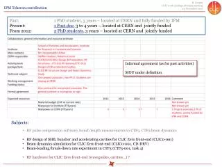
Past: 1 PhD student, 3 years – located at CERN and fully funded by IPM Present: 1 Post-doc , 3 to 4 years – located at CERN and jointly funded From 2012: 2 PhD students , 3 years – located at CERN and jointly funded. Informal agreement (as for past activities) MOU under definition.

E N D
Past: 1 PhD student, 3 years – located at CERN and fully funded by IPM Present: 1 Post-doc, 3 to 4 years – located at CERN and jointly funded From 2012: 2 PhD students, 3 years – located at CERN and jointly funded Informal agreement (as for past activities) MOU under definition • Subjects: • RF pulse compression software, bunch length measurements in CTF3, CTF3 beam dynamics • RF design of SHB, buncher and accelerating cavities for CLIC Zero front-end (CLIC0-001) • Beam dynamics simulation for CLIC Zero front-end (CLIC0-001, CD-DRV) • Beam-loading/break-down rate experiment in CTF3 (CTF3-001, task 4) • RF hardware for CLIC Zero front-end (waveguides, cavities…) ?
Parametric study, optimization and RF design of CLIC Zero front-end SHB cavities It is possible to reduce the power a little. For example to 75 KW from 80 KW in last slide. After choosing the structure we can work to optimize cells depend on all parameters affect the design like beam loading, HOMs, minimum wall thickness for cooling water pipe holes and ... It is the definition of drain time as was introduce by L. Thorndahl et al.[2] . This time is used to find the number of bunches passages during phase switching. For FTW case it is about 8% less (τ’≈9ns) and for BTW case it is about 20 % more than filling time(τ’≈12ns). LCWS 2011 - Granada
CLIC Drive Beam Front-end CLIC0-001 CLIC Drive Beam injector schematic layout Modulator-klystrons, 1 GHz TWTs, 500 MHz Magnetic chicane, diag. & collimation Quads Quads Gun PB Buncher Acc. Structures SHB 1-2-3 ~ 140 keV ~ 6 MeV ~ 30 MeV
BDR with beam loading DELAY LOOP • Beam loading reduces field => BDR lower? • CLEX probe beam current limited => use CTF3 drive beam andklystron-driven X-band structure in the old ‘30 GHz PETS’ line • 30 GHz waveguide network has to be converted to X-band • Interface to regular structure test area and switchable connection to klystron • RF instrumentation from stand-alone power source • need manpower for the software and analysis COMBINER RING BL - BDR experiment DRIVE BEAM LINAC CLEX