Download

1 / 20
210 likes | 345 Views
Use of AP203 CAD Data for Engineering Analysis. Hans Peter de Koning - ESA/ESTEC - The Netherlands Hans-Peter.de.Koning@esa.int Sandrine Fagot - Simulog - France Sandrine.Fagot@simulog.fr STEP for Aerospace Workshop, NASA-JPL, 16-19 January 2001. Agenda.

E N D
Use of AP203 CAD Data for Engineering Analysis Hans Peter de Koning - ESA/ESTEC - The Netherlands Hans-Peter.de.Koning@esa.int Sandrine Fagot - Simulog - France Sandrine.Fagot@simulog.fr STEP for Aerospace Workshop, NASA-JPL, 16-19 January 2001
Agenda • Recap: Usage of CAD to create CAE model • Use of AP203 as input • Specific application for thermal-radiative CAE (ESARAD) • Real world example • Further plans STEP for Aerospace Workshop - NASA-JPL
Recap: Why use CAD geometry to construct CAE models? • Main objectives: • To reduce CAE model construction effort • To improve CAE model accuracy and fidelity • To transfer and retain product structure and part identification information • To improve consistency between CAE models for different engineering disciplines -- CAD model as ‘master digital mock-up’ • Avoid duplication of effort • If it has been modelled in CAD already, why do it again? • CAD modeller is probably richer in shape creation functionality than the CAE modeller STEP for Aerospace Workshop - NASA-JPL
Potential pitfalls with usage of CAD for CAE • CAE virtually always needs idealised shape • Idealised shape = geometric represention of the object under analysiswhich is appropriate, adequate and sufficiently detailedfor the analysis task at hand • Who said engineering is a hard science? • Lot of engineering judgement involved • Depends on environmental conditions, operational context • Depends on engineering life cycle stage • Nevertheless, still serious benefits from automated transfer of CAD models to CAE when used with caution STEP for Aerospace Workshop - NASA-JPL
Use of AP203 for CAD - CAE model transfer • Nearly all CAD tools now have reliable, good quality AP203 import/export functionality • Very attractive for CAE tools to support AP203 • Good investment: one interface supports all CAD tools • First import of AP203 models, later perhaps also export • But also problems • Most CAE tools can not directly handle all AP203 shapes • NURB curves and surfaces, trimming loops, general surface of revolution, etc. • Different CAD tools generate different AP203 models • For example: many different ways to define a cylindrical surface NURB = Non-Uniform Rational B-spline STEP for Aerospace Workshop - NASA-JPL
Specific Application: Thermal-radiative CAE • STEP AP203 model import and NURB processing capability for ESARAD • R&D activity in 2000 under ESA contract • ALSTOM Power Technology Centre (UK) • ESARAD tool vendor • Management, integration and test • Simulog (France) • AP203 to ESARAD import translator • Formal Software Construction Ltd. (UK) • ESARAD NURB surface processing ESARAD = Thermal-radiative analysis tool (Monte-Carlo raytracer) STEP for Aerospace Workshop - NASA-JPL
Usage scenario: Construct CAD/AP203 to ESARAD • Identify CAD model for export • Optionally prepare ‘CAE view’ in CAD tool • Suppress features, filter small details, flatten hierarchy, remove irrelevant parts • Export to STEP AP203 part 21 file • Translate AP203 model to native ESARAD model • Clean-up and adapt model in ESARAD modeller • Add thermal-radiative features • meshing, properties, environmental conditions, kinematics, ... • Ready to run ESARAD analysis STEP for Aerospace Workshop - NASA-JPL
Translate AP203 model to native ESARAD model (1) • Problem: Mapping of AP203 shapes to ESARAD shapes • ESARAD is a surface modeller • primitive surface shapes • triangular, rectangular, quadrilateral plate • disc (-sector, -annulus) • cylinder (-segment) • cone, sphere, paraboloid (-segment, truncated-) • compound surfaces (union of primitive or compound surfaces) • boolean cut surfaces (e.g. plate with circular hole) • Most CAD tools export AP203 evaluated BREP solid models • AP203 CC4, CC5, CC6 models with lots of advanced shapes using NURB, trimming loops, etc. STEP for Aerospace Workshop - NASA-JPL
Translate AP203 model to native ESARAD model (2) • Approach • Develop heuristic algorithm to recognise / deduct as much as possible primitive shapes in the CAD AP203 export • Transfer any remaining shapes as NURB surfaces (with trimming loops) • Retain model hierarchy and axis placements • Retain shape identification labels, etc. • Translator is a stand-alone Unix filter type tool • Simple, maintainable, easily extendible to support new output formats • Upgrade ESARAD to accept NURB surfaces • In shape definition, but also in ray-tracing algorithm! STEP for Aerospace Workshop - NASA-JPL
Translate AP203 model to native ESARAD model (3) • Target Catia v4 as first CAD export tool for testing • Is most used CAD tool in European space industry • Developed Catia generated AP203 test suite • Artificial little CAD models containing different ways to construct the primitive shapes (also asking different engineers) • Replicated the STEP-TAS test suite using Catia • Real world CAD models, including a complete detailed spacecraft CAD model (generates more than 220,000 instances in Part 21 file) • Developed heuristic algorithm • As much as possible works on generic STEP p42 concepts • As little as possible tuned to Catia specific constructs / oddities • Outcome is a translator that works! STEP for Aerospace Workshop - NASA-JPL
Translate AP203 model to native ESARAD model (4)Example from test-suite STEP for Aerospace Workshop - NASA-JPL
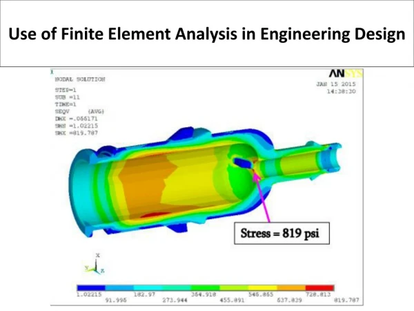
Real World Example: Test jig for METOP spacecraft • METOP: earth observation satellite for Eumetsat • Sun-synchronous polar orbit - similar to ERS, Envisat, NASA-EOS • Modelled in detail in ESARAD (more than 4000 surfaces) • Currently in Phase C/D - Starting thermal balance test predictions • Task: Create ESARAD model of test jig • Test jig for thermal test, containing cold targets and guard heaters • Complicated shape - geometry available in Catia v4 STEP for Aerospace Workshop - NASA-JPL
Real World Example: Test jig for METOP spacecraftAP203 export from Catia ISO-10303-21; HEADER; FILE_DESCRIPTION((''), '1'); FILE_NAME('METOP FRAME UPPER ', '2000-09-25T09:11:38+02:00', (''), (''), 'CATIA.STEP INTERFACE', 'CATIA SOLUTIONS V4 RELEASE 2.0 FR 4.2.0', ''); FILE_SCHEMA(('CONFIG_CONTROL_DESIGN')); ENDSEC; DATA; #1=APPLICATION_CONTEXT('configuration controlled 3D designs of mechanical parts and assemblies'); #2=APPLICATION_PROTOCOL_DEFINITION('international standard','config_control_design',1994,#1); #3=PERSON('111111','Last_Name','First_Name',$,$,$); ... #650=VERTEX_POINT('NONE',#649); #651=B_SPLINE_CURVE_WITH_KNOTS('*CRV273',1,(#652,#653),.UNSPECIFIED.,.U.,.U.,(2,2),(0.00000000000,1.00000000000),.UNSPECIFIED.); #652=CARTESIAN_POINT('NONE',(-6663.00000000,2.51588360813,-18.6521285509)); … #16704=TRIMMED_CURVE('*CRV558',#16703,(90.0000000000),(108.628958036),.T.,.UNSPECIFIED.); #16705=B_SPLINE_CURVE_WITH_KNOTS('*CRV559',5,(#16706,#16707,#16708,#16709,#16710,#16711,#16712,#16713,#16714,#16715,#16716,#16717),.UNSPECIFIED.,.U.,.U.,(6,3,3,6),(0.00000000000,1.00000000000,1.70960642440,2.31910764281),.UNSPECIFIED.); STEP for Aerospace Workshop - NASA-JPL
Real World Example: Test jig for METOP spacecraftTranslation into ESARAD definition language /* ESARAD GENERATED FILE FROM STEP AP203 FILE */ /* ------------------------------------------ */ /* INFORMATION ON STEP AP203 FILE : */ /* COMPANY : */ /* LOCATION : location */ /* SERVICE : service name */ /* PERSON : */ /* PROJECT : project name */ /* PREPROCESSOR_VERSION : CATIA.STEP INTERFACE */ /* ORIGINATING_SYSTEM : CATIA SOLUTIONS V4 RELEASE 2.0 FR 4.2.0 */ /* DATE : 25/9/2000 */ BEGIN_MODEL MetopFrameUpper SHELL generated_id_1; generated_id_1 = SHELL_DISC( point1 = [ -6.763000, 1.125000, 0.160000], point2 = [ -6.762765, 1.125882, 0.159592], point3 = [ -6.763000, 1.127516, 0.165447], point5 = [ -6.763000, 1.122903, 0.155461]); SHELL generated_id_3; generated_id_3 = SHELL_NURB_SURFACE( u_dim = 9, v_dim = 2, points = {[-6.727706, 1.254837, 0.093422], [-6.698294, 1.365131, 0.042479], [-6.733537, 1.256119, 0.092830], [-6.704126, 1.366413, 0.041887], [-6.733537, 1.258635, 0.098277], [-6.704126, 1.368929, 0.047334], [-6.733537, 1.261150, 0.103724], [-6.704126, 1.371445, 0.052781], [-6.727706, 1.259869, 0.104316], [-6.698294, 1.370163, 0.053373], [-6.721874, 1.258587, 0.104908], [-6.692463, 1.368881, 0.053965], [-6.721874, 1.256071, 0.099461], [-6.692463, 1.366365, 0.048518], [-6.721874, 1.253555, 0.094014], [-6.692463, 1.363850, 0.043071], [-6.727706, 1.254837, 0.093422], [-6.698294, 1.365131, 0.042479]}, weights = {1.000000, 1.000000, 0.707107, 0.707107, 1.000000, 1.000000, 0.707107, 0.707107, 1.000000, 1.000000, 0.707107, 0.707107, 1.000000, 1.000000, 0.707107, 0.707107, 1.000000, 1.000000}, u_degree = 2, v_degree = 1, u_knots = {0.000000, 0.000000, 0.000000, 1.570796, 1.570796, 3.141593, 3.141593, 4.712389, 4.712389, 6.283185, 6.283185, 6.283185}, v_knots = {0.150000, 0.150000, 0.275000, 0.275000}, num_loops = 1, loops = { DEFINE_NURB_TRIM_LOOP ( num_curves = 4, curves = { STEP for Aerospace Workshop - NASA-JPL
Produced with first beta version of translator Sep-2000 All NURB-related shapes removed, because at that stage not yet supported in ESARAD visualisation and ray-tracing Still a large amount of useful reference surfaces and points Real World Example: Test jig for METOP spacecraftRaw AP203 export in ESARAD STEP for Aerospace Workshop - NASA-JPL
After adaptation in ESARAD modeller and adding thermal features Estimated 25% reduction in model construction effort So, even without NURB support already significant savings Real World Example: Test jig for METOP spacecraftFinal jig model positioned on spacecraft STEP for Aerospace Workshop - NASA-JPL
Ray-tracing with NURB surfaces • Status: • Algorithm works functionally • First round of performance tuning done • Just before workshop delivered to ESA for acceptance testing • Functionality will be incorporated in next industrial release of ESARAD STEP for Aerospace Workshop - NASA-JPL
Example NURB shapes now supported in ESARAD ray-tracing Some X-38-like concept -- no status -- just a test model STEP for Aerospace Workshop - NASA-JPL
Conclusions • Import from CAD to ESARAD is working well • Could not have been done sensibly without STEP • Very promising development • Emphasis is on improving the engineering analysis cycle • NURB support in ESARAD is for most cases not really needed from the thermal analysis point of view • Striving to increase the efficiency and effectivity of the engineer, not optimising on CPU or other computer resource usage • However, high-fidelity NURB surfaces can be appropriate in some special cases thermal or thermal/optical analysis • Mirror optics • Parasitic heatloads infra-red sensors, passive cooler baffles STEP for Aerospace Workshop - NASA-JPL
Future • Complete testing • Testing with exports from other CAD packages - enhancement of heuristic shape recognition • Improve transfer of product and part info (meta data) • AP203 to STEP-TAS converter? • AP203 import and NURB ray-tracing in next major industrial release of ESARAD STEP for Aerospace Workshop - NASA-JPL