CSC Track Finder upgrade
160 likes | 292 Views
CSC Track Finder upgrade. Focusing on algorithm logic now Design Performance evaluation Hardware details will come later. CSC Track Finder upgrade. Current design is totally adequate for LHC luminosity 2 LCTs (di-muon signal) + 1 (background) = 3 LCTs per Port Card per BX

CSC Track Finder upgrade
E N D
Presentation Transcript
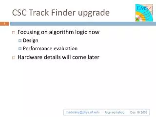
CSC Track Finder upgrade • Focusing on algorithm logic now • Design • Performance evaluation • Hardware details will come later Rice workshop
CSC Track Finder upgrade • Current design is totally adequate for LHC luminosity • 2 LCTs (di-muon signal) + 1 (background) = 3 LCTs per Port Card per BX • With luminosity upgrade, we expect ~7 LCTs per Port Card per BX. • Preliminary simulated data, no measurements so far • Reality could be worse • Port Card becomes a bottleneck • Solution: • Keep 2 Trigger Primitives per chamber • Bring all LCTs to SP (18 per Port Card per BX), no filtering • May keep the filtering option in Port Cards, in case it’s needed • See this talk by Darin Acosta for explanation of above numbers • Based on simulations performed by A. Safonov and V. Khotilovich (TAMU)
SP upgrade Current SP logic structure Conversion of trigger primitives to coordinates BX adjustment to 2nd trig. primitive Pt, φ, η calculation Multiple Bunch Crossing Analysis Extrapolation units Track assembly Sorting, ghost cancellation
Trig. Primitives Coordinates • Currently performed in large 2-stage LUTs • Unacceptable for upgrade – too much memory • 4MB per trig. primitive • 6 times more trig. primitives in upgraded design • Need ~400 MB per SP Wiregroup pattern φ Strip pattern LUT η Chamber ID
Trig. Primitives Coordinates • For upgrade: • Make conversion inside FPGA • Combine LUTs and logic to reduce memory size • We receive Trig. Primitives from all chambers • no need to analyze Chamber ID • saves precious LUT input bits • Use different angular coordinates – φ with half-strip resolution and θ • Why θ ? • Allows for uniform angular extrapolation windows, no need to adjust them depending on θ • Why φ with half-strip resolution? • Makes conversion easier, for 80-strip 10° chambers (ME1/2, ME2/2, ME3/2, ME4/2) as easy as one addition with fixed value. • Easier to handle in FPGA
Wiregroup θ θ1 8-bit Wiregroup 5 to 7-bit θ 8-bit Wiregroup 6-bit + LUT 32 to 128 cells LUT θ2 8-bit + Strip1 6-bit θ conversion all chambers except ME1/1 θ corrections 4-bit LUT WG MSB 2-bit Strip2 6-bit WG1 θ1 WG1 θ2 LUT WG MSB 2-bit WG2 θ1 WG2 θ2 ME1/1 θ conversion θ corrected and duplicated because of wire tilt (if chamber has 2 trig. primitives)
Strip φ Half-Strip 7 or 8-bit φ in sector 10-bit ×F + Initial φ 10-bit (fixed) corrected φ in sector 12-bit CLCT pattern 4-bit φ correction 2-bit LUT Use built-in multiplier or LUT. “F” factor depends on chamber type
Pattern-based detection • Investigating another approach: • Pattern-based detection • Separately in φ and θ • Once the patterns are detected, merge them into complete 3-D tracks • Benefits: • Logic size reduction • Size does not explode if 3 track segments per chamber are needed • Certain processing steps become “natural”, logic for them is greatly simplified or removed • Multiple Bunch Crossing Analysis • Ghost Cancellation • Assigning timing on second track segment
Pattern-based detection • Target: importing all available trig. primitives from all CSCs • Status: this section complete (initial attempt) • Starting integration and tests with CMSSW very soon Trig. primitives to θ and φconversion Raw hit construction Raw hit persistence (time extension) φ and θ pattern detectors best pattern selectors (3 in each zone, total 12 best φ and 18 best θ patterns) φ and θ pattern merging into 12 track candidates selection of best three tracks, precise φ, η, Pt assignment
Raw hit reconstruction: layers and zones • 4 layers of chambers make up detector layers • Split the sector into zones according to phi and theta coverage theta phi
Zone boundaries Phi 9 bit Theta 7 bit
Raw hit construction • Based on simple decoders • Phi and theta coordinates converted to positional codes (hits) • Put into zones according to chamber that they came from
Raw hit persistence • Each raw hit is time-extended to 4 BX • The hits overlap in time, so delayed track segments can be taken into account by pattern detectors • This used to be BXA functionality
Pattern detectors • Phi pattern detection is in double strips, to save logic • Detection precision seems to be sufficient • Full 12-bit phi will be assigned to the best tracks • Phi patterns are constructed so that: • They accommodate max 10 degree bending (ME1-ME2) • High-PT (straightest) tracks are detected most precisely • As bending increases, the precision becomes worse • Minimum two layers must be hit • Quality code: • The more layers – the better • Patterns with ME1 hit have priority • Theta patterns are similar but simpler • No bending in theta direction ME 1234 Station 16 8 4 2 1 1 1 2 4 8 16 Number of di-Strips ORed One of the patterns Possible φ pattern envelope structure
Remaining steps • Best pattern selection in each zone • Merging phi and theta patterns into 12 track candidates • Three best tracks selection • Precise parameter assignment
Performance evaluation • Bobby Scurlockhas integrated code into CMSSW • Working on pattern mask optimization now • Getting ready for performance plots • Meanwhile: • new Verilog to CPP converter is finished: features: • supports most of Verilog 2001 features, including test fixtures • generates compact C++ that compiles with GCC and Microsoft VC++ • generated C++ is traceable to the original Verilog code • transfers author's comments from the source Verilog to the generated C++ • expands Verilog by allowing array inputs/outputs • performance of the generated C++ looks OK, to be evaluated later • adapting upgraded TF logic design for the new converter is in progress, will be finished soon. Rice workshop