Download
1 / 26
260 likes | 283 Views
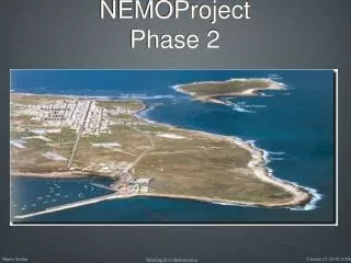
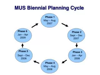
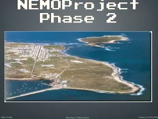
NEMOProject Phase 2. Nemo Phase 2 Composizione. Stazione a terra Survey Autorizzazioni e permessi Cavo elettro-ottico Branching Units Cable Terminations Assembly Operazioni Marine Operazioni a terra Shore Power Feed Equipment DC/DC Converter. Nemo Phase 2 Shore Station.

E N D
Nemo Phase 2 Composizione • Stazione a terra • Survey • Autorizzazioni e permessi • Cavo elettro-ottico • Branching Units • Cable Terminations Assembly • Operazioni Marine • Operazioni a terra • Shore Power Feed Equipment • DC/DC Converter
Nemo Phase 2 Shore Station Ingresso Cavo Elettro-Ottico
Nemo Phase 2 Backbone Cable 17 mm Copper Shield 1.6 Ω/km 0.90-0.57 Kg/m 70 kN 30 kN 500LW/900DA mm 10 kV 1.600 V 10 A 100 kW • Cable Outer Diameter • Conductor Diameter • DC Resistance • Weight Air/Water • Cable Breaking load • Operating Tension • Min. Dynamic Bending • Working Voltage • Drop Voltage • Current • Power
Storey power load (4 OM + storey electronics + additional sensors) 20 W • Nemo Phase 2 Power Budget x 16 storeys 320 W + additional power load at the tower base (electronics, sensors, …) 100 W Total power load per tower 420 W x 81 towers (5.184 OM) 34 kW + JB power load (electronics, sensors, …), 300 W per JB 3 kW + additional power load as spare or associate science 10 kW Total power load ~50 kW
Nemo Phase 2 Branching Unit Interdisciplinary Activity Requests Electro-Optics Characteristics Intermediate Branching Unit • Depth - 100 m Power 250 W DC 1 Fiber Optic ITU.T G.655 • Depth - 2.000 m Power 500 W DC 1 Fiber Optic ITU.T G.655
Nemo Phase 2 System Layout Active BU Passive BU Passive BU 100 m 100 m 20 Km 40 Km 80 Km 100 m 100 m 100 m 7 Km PFE Current Probe Trunk End#3 Trunk End#1 Trunk End#2 DC/DC 12 Km 3.500 m Depth 100 m Depth 2.000 m Depth
Nemo Phase 2 Marine Operations • Project Management • Desk top study • Environmental Impact Assessment • Authorization and permitting service • Cable Route Survey • Marine Geophysical Survey • Topographic Landing Area Survey • Diver Survey • Reporting and Charting • Route Clearance • Pre Lay Grapnel Run • Marine installation • Cable loading • Cable main lay • Beach work and cable protection • Post Lay Works • Final Reporting and Charting
Nemo Phase 2 Survey • Cable Route Survey • Marine Geophysical Survey • Topographic Landing Area Survey • Diver Survey • Reporting and Charting Catania Sintesi dei risultati • Confronto tra la rotta contrattuale e la rotta finale • Rotta Contrattuale • Rotta Finale e Diagramma di Linea • Differenze tra la Rotta Contrattuale e la Rotta Finale • Lista dei Contatti Sonar • Lista dei Cavi Incrociati • Datum orizzontale e verticale • Topografia dell’area di approdo di Capo Passero Capo Passero • Risultati di dettaglio • Rotta percorsa durante il Survey • Descrizione degli allegati cartografici • Campionamenti del fondo marino • Attività di possibile interferenza con il collegamento • Fattori antropici • Attività di pesca • Servizi esistenti ed in progetto • Relitti ed impedimenti alla navigazione • Dati sui danni subiti dai cavi sottomarini nell’area interessata dal cavo
Nemo Phase 2 Power Feed Equipment Block Diagram CONTROLLER SHELF PU Controller Power In Converter to line PU Monitors Common Monitors Cable Termination Cubicle n….. ALARM CONCENTRATOR SHELF Converter system earth PU OPTICAL FIBER DISTRIBUTION UNIT Dummy Load routing switch CABLE TERMINATING SHELF EARTH ISOLATION SHELF
Nemo Phase 2 BMH Capo Passero Approdo Catania Approdo
High power flying ROV receptacle assembly • Nemo Phase 2 Passive BU Electro-Optical Flying ROV receptacle assembly Specifications: ・ Dimensions 2.0x0.5x2.0(m) ・ Weight : 1200kg (in Air) ・ Pressure Resist : 4000m
Nemo Phase 2 Active Branching Unit Control and Power Distribution
Nemo Phase 2 DFME Auto Latching Branching Unit >BU Supervisory Functions 1>1.2 s Recovery Driver Command Sequence 28.8 ms 3 X Current 3 X Apply Current Sharing Share Request 1>1.2 s Main Driver Command Sequence 28.8 ms 3 X Confirm 3 X Configuration Configuration Request Request Main Driver Recovery Driver Commands Commands Command Sequence Delay between 75 - 100 s
Nemo Phase 2 Active Branching Unit Fibres ReF Optics Tray Recovery Zeners Recovery receiver Main Smoothing Board Fibres Recovery Chassis D (Earth) C Main Chassis A B Blank Chassis Main Driver ReE ReD Pin Diodes RLA ReC RLB Splice Tray Surge Coil Main Bridge Rectifier Main Zero Detect and Resistor Box Main Zeners Main Receiver
0.27m 5-7m 1m • Nemo Phase 2 Cable Termination Assembly Sea Hearth Connection CTA
Cable In Cable Out DC/DC 5-10 kW DC/DC 5-10 kW VDC 10 kV VDC 10 kV 400 Vdc Out Fibre Out 400 Vdc Out Fibre Out ROV connector ROV connector JB DC/AC • Nemo Phase 2 Cable Termination Assembly To shore
Nemo Phase 2 DC/DC Converter 10kV/400V Internal supply Input filter Output filter 200V 50V Tx Current sense Primary switching Synchronous rectifier Gate Drive Sub Converter Topology used in the Neptune Project by JPL NASA Low stress design 600V transistors used to switch 200V Devices capable of working at 100oC used at 36oC
10kV 400V Control / start-up 1 Control / start-up 2 Control / start-up 3 Control / start-up 4 Control / start-up 5 Control / start-up 6 10kV 400V Control / start-up 1 Control / start-up 2 Control / start-up 3 Control / start-up 4 Control / start-up 5 Control / start-up 6 • Nemo Phase 2 DC/DC Design In the event of the FET failing Open circuit the diodes fail short circuit, typically 0.5 to 1 ohm Output diodes allows Large large scale failure of sub converter output sections or control with only reduced output current X-Ray showing plate construction. Without bond wires, rupture current grater than 150A Sub converters input sections fail short circuit allowing large to fail without loss of output
Physical Construction of First MARS Converter Large diameter sea case is expensive and difficult to handle PCBs are too large for most manufactures, limited number of suppliers PCBs are too large for pick and place assembly machines, must be hand built
Nemo Phase 2 DC/DC Converter Project Compact Physical Construction Pressure compensation using bellows Flourinert FC77 filled housing PCBs perpendicular to pressure vessel Ethylene Propylene O-Rings External connections
V Shore Power Supply Node Converters - + 10 kV - I + 10 A Anode Coating Anode Cathode Backfill Sea Water Cathode Coating Soil Saturated Sand • Nemo Phase 2 Ground Return Electrodes •Single conductor cable necessitates ground return electrodes •Similar applications include: –Gas generation –HVDC Power Distribution –Trans-ocean telecom systems –Impressed current cathodic protection Ground Return Circuit
Nemo Phase 2 Remote Earth Electrode Ti grade 2 electrode structure Insulated steel strength termination Standard cable buffer Earth conductor +redundancy Mixed metal oxide coating Elastomer bend limiter Active surface of electrode LW cable core passes through electrode. Outer armour wires terminated in a similar way to an armoured cable joint
Nemo Phase 2 Tower Power Distribution 400 VAC Benthosphere Electric load storey 16 ~ ~ - Tower storeys FCM (Floor Control Module) Electric load storey 3 ~ ~ - Electric load storey 2 ~ ~ - ~ ~ Electric load storey 1 - Base Tower CONNECTION Second. JB - base tower Electro-optical cable Vin 400VAC Secondary JB